ODM
RECOMMENDED STANDARD
CCSDS 502.0-B-3
BLUE BOOK
April 2023
STATEMENT OF INTENT
The Consultative Committee for Space Data Systems (CCSDS) is an organization officially established by the management of its members. The Committee meets periodically to address data systems problems that are common to all participants, and to formulate sound technical solutions to these problems. Inasmuch as participation in the CCSDS is completely voluntary, the results of Committee actions are termed Recommended Standards and are not considered binding on any Agency.
This Recommended Standard is issued by, and represents the consensus of, the CCSDS members. Endorsement of this Recommendation is entirely voluntary. Endorsement, however, indicates the following understandings:
Whenever a member establishes a CCSDS-related standard, this standard will be in accord with the relevant Recommended Standard. Establishing such a standard does not preclude other provisions which a member may develop.
Whenever a member establishes a CCSDS-related standard, that member will provide other CCSDS members with the following information:
The standard itself.
The anticipated date of initial operational capability.
The anticipated duration of operational service.
Specific service arrangements shall be made via memoranda of agreement. Neither this Recommended Standard nor any ensuing standard is a substitute for a memorandum of agreement.
No later than five years from its date of issuance, this Recommended Standard will be reviewed by the CCSDS to determine whether it should: (1) remain in effect without change; (2) be changed to reflect the impact of new technologies, new requirements, or new directions; or (3) be retired or canceled.
In those instances when a new version of a Recommended Standard is issued, existing CCSDS-related member standards and implementations are not negated or deemed to be non- CCSDS compatible. It is the responsibility of each member to determine when such standards or implementations are to be modified. Each member is, however, strongly encouraged to direct planning for its new standards and implementations towards the later version of the Recommended Standard.
FOREWORD
This document is a Recommended Standard for Orbit Data Messages and has been prepared by the CCSDS. The set of orbit data messages described in this Recommended Standard is the baseline concept for trajectory representation in data interchange applications that are cross-supported between Agencies of the CCSDS.
This Recommended Standard establishes a common framework and provides a common basis for the interchange of orbit and orbit-relevant data. It allows implementing organizations within each Agency to proceed coherently with the development of compatible derived standards for the flight and ground systems that are within their cognizance. Derived Agency standards may implement only a subset of the optional features allowed by the Recommended Standard and may incorporate features not addressed by this Recommended Standard.
Attention is drawn to the possibility that some of the elements of this document may be the subject of patent rights. CCSDS has processes for identifying patent issues and for securing from the patent holder agreement that all licensing policies are reasonable and non- discriminatory. However, CCSDS does not have a patent law staff, and CCSDS shall not be held responsible for identifying any or all such patent rights.
Through the process of normal evolution, it is expected that expansion, deletion, or modification of this document may occur. This Recommended Standard is therefore subject to CCSDS document management and change control procedures, which are defined in Organization and Processes for the Consultative Committee for Space Data Systems (CCSDS A02.1-Y-4). Current versions of CCSDS documents are maintained at the CCSDS Web site:
Questions relating to the contents or status of this document should be sent to the CCSDS Secretariat at the email address indicated on page i.
At time of publication, the active Member and Observer Agencies of the CCSDS were:
Member Agencies
Agenzia Spaziale Italiana (ASI)/Italy.
Canadian Space Agency (CSA)/Canada.
Centre National d’Etudes Spatiales (CNES)/France.
China National Space Administration (CNSA)/People’s Republic of China.
Deutsches Zentrum für Luft- und Raumfahrt (DLR)/Germany.
European Space Agency (ESA)/Europe.
Federal Space Agency (FSA)/Russian Federation.
Instituto Nacional de Pesquisas Espaciais (INPE)/Brazil.
Japan Aerospace Exploration Agency (JAXA)/Japan.
National Aeronautics and Space Administration (NASA)/USA.
UK Space Agency/United Kingdom.
Observer Agencies
Austrian Space Agency (ASA)/Austria.
Belgian Science Policy Office (BELSPO)/Belgium.
Central Research Institute of Machine Building (TsNIIMash)/Russian Federation.
China Satellite Launch and Tracking Control General, Beijing Institute of Tracking and Telecommunications Technology (CLTC/BITTT)/China.
Chinese Academy of Sciences (CAS)/China.
China Academy of Space Technology (CAST)/China.
Commonwealth Scientific and Industrial Research Organization (CSIRO)/Australia.
Danish National Space Center (DNSC)/Denmark.
Departamento de Ciência e Tecnologia Aeroespacial (DCTA)/Brazil.
Electronics and Telecommunications Research Institute (ETRI)/Korea.
European Organization for the Exploitation of Meteorological Satellites (EUMETSAT)/Europe.
European Telecommunications Satellite Organization (EUTELSAT)/Europe.
Geo-Informatics and Space Technology Development Agency (GISTDA)/Thailand.
Hellenic National Space Committee (HNSC)/Greece.
Hellenic Space Agency (HSA)/Greece.
Indian Space Research Organization (ISRO)/India.
Institute of Space Research (IKI)/Russian Federation.
Korea Aerospace Research Institute (KARI)/Korea.
Ministry of Communications (MOC)/Israel.
Mohammed Bin Rashid Space Centre (MBRSC)/United Arab Emirates.
National Institute of Information and Communications Technology (NICT)/Japan.
National Oceanic and Atmospheric Administration (NOAA)/USA.
National Space Agency of the Republic of Kazakhstan (NSARK)/Kazakhstan.
National Space Organization (NSPO)/Chinese Taipei.
Naval Center for Space Technology (NCST)/USA.
Netherlands Space Office (NSO)/The Netherlands.
Research Institute for Particle & Nuclear Physics (KFKI)/Hungary.
Scientific and Technological Research Council of Turkey (TUBITAK)/Turkey.
South African National Space Agency (SANSA)/Republic of South Africa.
Space and Upper Atmosphere Research Commission (SUPARCO)/Pakistan.
Swedish Space Corporation (SSC)/Sweden.
Swiss Space Office (SSO)/Switzerland.
United States Geological Survey (USGS)/USA.
DOCUMENT CONTROL
Document |
Title |
Date |
Status |
|---|---|---|---|
CCSDS 502.0-B-1 |
Orbit Data Messages, Issue 1 |
September 2004 |
Original issue, superseded |
CCSDS 502.0-B-2 |
Orbit Data Messages, Recommended Standard, Issue 2 |
November 2009 |
Issue 2, superseded |
CCSDS 502.0-B-3 |
Orbit Data Messages, Recommended Standard, Issue 3 |
April 2023 |
Current issue: changes from the previous issue are documented in annex J (note). |
CCSDS 502.0-B-3 EC 1 |
Editorial change 1 |
May 2023 |
Corrects errant cross-reference links, adjusts some minor format and page-layout elements. |
Note
Changes from the previous issue are too numerous to permit meaningful application of change bars.
1 INTRODUCTION
1.1 PURPOSE AND SCOPE
This Orbit Data Messages (ODM) Recommended Standard specifies four standard message formats for use in transferring spacecraft orbit information between space agencies and commercial or governmental spacecraft operators: The Orbit Parameter Message (OPM), the Orbit Mean-Elements Message (OMM), the Orbit Ephemeris Message (OEM), and the Orbit Comprehensive Message (OCM). Such exchanges are used for:
pre-flight planning for tracking or navigation support;
scheduling tracking support;
carrying out tracking operations (sometimes called metric predicts);
performing orbit comparisons;
carrying out navigation operations such as orbit propagation and orbit reconstruction;
assessing mutual physical and electromagnetic interference among satellites orbiting the same celestial body (primarily Earth, Moon, and Mars at present);
performing orbit conjunction (collision avoidance) studies; and
developing and executing collaborative maneuvers to mitigate interference or enhance mutual operations.
This Recommended Standard includes sets of requirements and criteria that the message formats have been designed to meet. For exchanges in which these requirements do not capture the needs of the participating agencies and satellite operators, another mechanism may be selected.
The ODM Recommended Standard is an international standard published under the auspices of CCSDS and International Standards Organization (ISO) Technical Committee 20, Subcommittee 13, developed jointly and in concert with the ISO TC20/SC14. As such, this CCSDS standard is also properly labeled as ISO 26900.
The recommended Orbit Data Message format is ASCII (reference [4]).
This ODM document describes both ‘Keyword = Value Notation’ (KVN) as well as Extensible Markup Language (XML) (reference [5]) formatted messages. Selection of KVN or XML format should be mutually agreed between message exchange partners.
Note
As currently specified, an OPM, OMM, or OEM file is to represent orbit data for a single spacecraft, and the OCM is to represent orbit data for either a single spacecraft or single parent spacecraft of a parent/child spacecraft deployment scenario. It is possible that the architecture may support multiple spacecraft per file; this could be considered in the future.
1.2 APPLICABILITY
The Orbit Data Message family of standardized orbit messages is applicable to all phases of the spacecraft and launch vehicle life cycle. The rationale behind the design of each orbit data message is described in annex E and may help the application engineer to select a suitable message. Definition of the orbit accuracy underlying a particular orbit message is outside of the scope of this Recommended Standard and should be mutually agreed upon between message exchange partners (or specified via COMMENT sections in the message itself). Applicability information specific to each orbit data message format appears in sections 3, 4, 5, and 6, as well as in annex subsections E2.4 and E2.5.
This Recommended Standard is applicable only to the message format and content, but not to its transmission. The transmission of the message between agencies and operators is outside the scope of this document and should be mutually agreed between message exchange partners.
Description of the message formats based on the use of XML is detailed in section 8.
1.3 RATIONALE
This update to version 2 of the Orbit Data Messages adds a fourth message type, the OCM, based on collaboration of the CCSDS Navigation Working Group and the ISO Technical Committee 20, Subcommittee 14, Working Group 3 (ISO TC20/SC14/WG3). A full list of the changes in this document is in annex J.
1.4 DOCUMENT STRUCTURE
Section 2 provides a brief overview of the CCSDS-recommended Orbit Data Message types, the OPM, OMM, OEM, and OCM.
Section 3 provides details about the structure and content of the OPM.
Section 4 provides details about the structure and content of the OMM.
Section 5 provides details about the structure and content of the OEM.
Section 6 provides details about the structure and content of the OCM.
Section 7 discusses the syntax considerations of the set of Orbit Data Messages (OPM, OMM, OEM, and OCM).
Section 8 provides details on the XML instantiations of the OPM, OMM, OEM, and OCM.
Following the principal content of the document, there are several annexes, both normative and informative, to guide the ODM user.
1.5 CONVENTIONS AND DEFINITIONS
1.5.1 NOTATION
1.5.1.1 Unit Notations
The following conventions for unit notations apply throughout this Recommended Standard, with message-specific guidance provided in 7.7. Units are drawn from the International System of Units (SI); units are either SI base units, SI derived units, or units outside the SI that are accepted for use with the SI (reference [1]). Except as noted, the units used within this document are as follows:
d: days, 86400 SI seconds;
kg: kilograms;
km: kilometers;
m: meters;
n/a: (units are not applicable);
%: percent;
s: SI seconds;
SFU: Solar Flux Units, equivalent to 10-22 W/(m2*Hz);
W: watts.
1.5.1.2 General
The following notational conventions are used in this document:
multiplication of units is denoted with a single asterisk ‘*’ (e.g., ‘kg*s’);
exponents of units are denoted with a double asterisk ‘**’ (e.g., m2 = m**2);
square roots of units are denoted by the same exponent notation of a double asterisk ‘**’ (e.g., \(\sqrt{km}\) = km**0.5);
division of units is denoted with a single forward slash ‘/’ (e.g., m/s);
the usual order of operations ordering applies (e.g., exponents before multiplication).
1.5.2 NOMENCLATURE
1.5.2.1 Normative Text
The following conventions apply for the normative specifications in this Recommended Standard:
the words ‘shall’ and ‘must’ imply a binding and verifiable specification;
the word ‘should’ implies an optional, but desirable, specification;
the word ‘may’ implies an optional specification;
the words ‘is’, ‘are’, and ‘will’ imply statements of fact.
Note
These conventions do not imply constraints on diction in text that is clearly informative in nature.
1.5.2.2 Informative Text
In the normative sections of this document, informative text is set off from the normative specifications either in notes or under one of the following subsection headings:
Overview;
Background;
Rationale;
Discussion.
1.5.3 DEFINITIONS
For the purposes of this document, the following definitions apply:
the word ‘agencies’ may also be construed as meaning ‘satellite operators’ or ‘satellite service providers’;
the word ‘participant’ denotes an entity that can acquire or broadcast navigation messages and/or radio frequencies, for example, a spacecraft, a tracking station, a tracking instrument, or an agency/operator;
the notation ‘n/aʼ signifies ‘not applicable’;
depending on context, the term ‘ODM’ may be used to refer to this document or may be used to refer collectively to the OPM, OMM, OEM, and OCM messages;
an ‘observation’ is a unique measurement set of a satellite’s state from a single sensor configuration at a single time (e.g., azimuth from a single sensor at a single time);
a ‘sensor track’ is a set of observations within a specified number of minutes for the same object, observed by the same sensor configuration, where each observation is within a specified number of minutes (which is dependent on the orbit regime of the object) of the other observations in the track (e.g., a set of 10 two-way transponder range measurements from the same sensor using the same transponder on the satellite), and where the number of minutes could alternately be defined as the time between start and stop of the measurement ‘session’ or signal modulation that enables metric tracking.
1.6 REFERENCES
The following publications contain provisions which, through reference in this text, constitute provisions of this document. At the time of publication, the editions indicated were valid. All publications are subject to revision, and users of this document are encouraged to investigate the possibility of applying the most recent editions of the publications indicated below. The CCSDS Secretariat maintains a register of currently valid CCSDS publications.
- [1] The International System of Units (SI). 8th ed., 2006; updated in 2014. Sèvres, France:
BIPM, 2006.
- [2] Time Code Formats. Issue 4. Recommendation for Space Data System Standards (Blue
Book), CCSDS 301.0-B-4. Washington, D.C.: CCSDS, November 2010.
- [3] “Online Index of Objects Launched into Outer Space.” United Nations Office for Outer
Space Affairs (UNOOSA). https://www.unoosa.org/oosa/osoindex/.
- [4] Information Technology—8-Bit Single-Byte Coded Graphic Character Sets—Part 1:
Latin Alphabet No. 1. International Standard, ISO/IEC 8859-1:1998. Geneva: ISO, 1998.
- [5] XML Specification for Navigation Data Messages. Issue 3. Recommendation for Space
Data System Standards (Blue Book), CCSDS 505.0-B-3. Washington, D.C.: CCSDS, May 2023.
- [6] Paul V. Biron and Ashok Malhotra, eds. XML Schema Part 2: Datatypes. 2nd ed. W3C
Recommendation.
- [7] IEEE Standard for Floating-Point Arithmetic. 3rd ed. IEEE Std 754-2019. New York:
IEEE, 2019.
- [8] Henry S. Thompson, et al., eds. XML Schema Part 1: Structures. 2nd ed. W3C
Recommendation.
- [9] Tracking Data Message. Issue 2. Recommendation for Space Data System Standards
(Blue Book), CCSDS 503.0-B-2. Washington, D.C.: CCSDS, June 2020.
- [10] Attitude Data Messages. Issue 1. Recommendation for Space Data System Standards
(Blue Book), CCSDS 504.0-B-1. Washington, D.C.: CCSDS, May 2008.
- [11] “CCSDS Navigation Standards Normative Annexes.” Space Assigned Numbers
Authority. https://sanaregistry.org/r/navigation_standard_normative_annexes.
- [12] Re-entry Data Message. Issue 1. Recommendation for (Blue Book), CCSDS 508.1-B-1.
Washington, D.C.: CCSDS, November 2019.
- [13] Pointing Request Message. Issue 1. Recommendation for (Blue Book), CCSDS 509.0-
B-1. Washington, D.C.: CCSDS, February 2018.
- [14] Conjunction Data Message. Issue 1. Recommendation for Space Data System
Standards (Blue Book), CCSDS 508.0-B-1. Washington, D.C.: CCSDS, June 2013.
2 OVERVIEW
2.1 ORBIT PARAMETER MESSAGE
An OPM specifies the position and velocity of a single object at a specified epoch. Optionally, osculating Keplerian elements may be provided. It should be noted that a sequence of OPMs for either a single object or for multiple objects can be aggregated into a single Navigation Data Message (NDM) XML file as described in 8.12 and shown in annex G. This message is suited to exchanges that (1) involve automated interaction and/or human interaction, and (2) do not require high-fidelity dynamic modeling.
The OPM requires the use of a propagation technique to determine the position and velocity at times different from the specified epoch, leading to a higher level of effort for software implementation than for the OEM.
The OPM also contains an optional 6x6 position/velocity covariance matrix that reflects the uncertainty of the orbit state and may be used in the propagation process to estimate future uncertainties.
The OPM allows for modeling of any number of maneuvers (as both finite and instantaneous events) and simple modeling of solar radiation pressure and atmospheric drag.
Though primarily intended for use by computers, the attributes of the OPM also make it suitable for applications such as exchanges by email, FAX, or voice, or applications in which the message is to be frequently interpreted by humans.
2.2 ORBIT MEAN-ELEMENTS MESSAGE
The OMM contains the orbital characteristics of a single object at a specified epoch, expressed in mean Keplerian elements: mean motion, eccentricity, inclination, right ascension of ascending node, argument of perigee, and mean anomaly. These are adequate for providing the initial mean state of analytical and semi-analytical orbit models. In addition, the OMM contains values for parameters that facilitate the modeling of non- conservative forces for various mean element theories.
It may be noted that a sequence of OMMs for either a single object or for multiple objects can be aggregated into a single NDM XML file as described in 8.12 and shown in annex G. The OMM is suited to exchanges that (1) involve automated interaction and/or human interaction, and (2) do not require high-fidelity dynamic modeling. Such exchanges may be inter-agency exchanges, or ad hoc exchanges among satellite operators when interface control documents have not been negotiated. Ad hoc interactions usually involve more than one satellite, each satellite controlled and operated by a different operating authority.
The OMM includes keywords and values that may be used to generate canonical NORAD Two Line Element (TLE) sets to accommodate the needs of heritage users (see annex H, reference [H3]). The OMM also contains an optional covariance matrix that reflects the uncertainty of the mean Keplerian elements. This information may be used to determine contact parameters that encompass uncertainties in predicted future states of orbiting objects of interest.
This message is suited for directing antennas and planning contacts with satellites. It is not recommended for assessing mutual physical or electromagnetic interference among Earth- orbiting spacecraft, developing collaborative maneuvers, or propagating precisely the orbits of active satellites, inactive man-made objects, and near-Earth debris fragments. It is not suitable for numerical integration of the governing equations.
Though primarily intended for use by computers, the attributes of the OMM also make it suitable for applications such as exchanges by email, FAX, or voice, or applications in which the message is to be frequently interpreted by humans.
2.3 ORBIT EPHEMERIS MESSAGE
An OEM specifies the position and velocity of a single object at multiple epochs contained within a specified time range. It should be noted that a sequence of OEMs for either a single object or for multiple objects can be aggregated into a single NDM XML file as described in 8.12 and shown in annex G. The OEM is suited to exchanges that (1) involve automated interaction (e.g., computer-to-computer communication when frequent, fast automated time interpretation and processing is required), and (2) require higher fidelity or higher precision dynamic modeling than is possible with the OPM.
The OEM allows for dynamic modeling of any number of gravitational and non-gravitational accelerations. The OEM requires the use of an interpolation technique to interpret the position and velocity at times different from the tabular epochs.
The OEM also contains an optional covariance matrix that reflects the uncertainty of the orbit solution used to generate states in the ephemeris.
2.4 ORBIT COMPREHENSIVE MESSAGE
An OCM specifies position and velocity of either a single object or an en masse parent/child deployment scenario stemming from a single object. It should be noted that a sequence of OCMs for either a single object or for multiple objects can be aggregated into a single NDM XML file as described in 8.12 and shown in annex G.
The OCM aggregates and extends OPM, OEM, and OMM content in a single comprehensive hybrid message (file) and includes the following additional capabilities:
Optional Earth Orientation (UT1 and UTC) at a nearby (relevant) reference epoch;
Optional Leap second specification;
Optional area cross-sections for drag, Solar Radiation Pressure (SRP) perturbations modeling;
Optional spacecraft dimensions and orientation information for collision probability estimation;
Optional orbit states (specified using one or more of Cartesian and orbit elements and reference frames) for a single or parent object at either a single epoch or as a time history (ephemeris);
Optional covariance matrix of selectable/arbitrary order for a single or parent object at either a single epoch or as a time history (ephemeris) that reflects the uncertainty of the orbit solution or simulation used to obtain the nominal states in the orbit state(s);
Optional covariance content options (e.g., Cartesian 3x3, 6x6, 7x7, or any combination of order, reference frame, and orbit elements);
Optional maneuver specification (impulsive or finite burn);
Optional perturbations model specification;
Optional orbit determination data and metrics.
The OCM simultaneously emphasizes flexibility and message conciseness by offering extensive optional content while minimizing mandatory content. The OCM is well-suited for exchanges that (1) involve automated interaction (e.g., computer-to-computer communication when frequent, fast automated time interpretation and processing is required), and (2) involve regular orbit data transfer for numerous objects (e.g., 200,000) using minimal network bandwidth, disk storage, and quantity of files. The OCM allows the user, in a single message/file, to either embed high-fidelity orbit propagation into an ephemeris time history (akin to the OEM ephemeris) or specify orbital states that can be propagated with supplied perturbations model parameters (akin to OPM content), or both.
2.5 EXCHANGE OF MULTIPLE MESSAGES
For a given object, multiple OPM, OMM, or OEM messages may be provided in a message exchange session to achieve ephemeris fidelity requirements, whereas a single, self-contained OCM may be sufficient. If ephemeris information for multiple objects is to be exchanged, then multiple OPM, OMM, OEM, or OCM files must be used, with the exception that the OCM supports parent/child deployment scenario specifications in a single message.
2.6 DEFINITIONS
Definitions of time systems, reference frames, planetary models, maneuvers, and other fundamental topics related to the interpretation and processing of state vectors and spacecraft ephemerides are provided in reference [H1].
3 ORBIT PARAMETER MESSAGE
3.1 GENERAL
3.1.1 Orbit information may be exchanged between two participants by sending a state vector (see reference [H1]) for a specified epoch using an OPM. The message recipient must have an orbit propagator available that is able to propagate the OPM state vector to compute the orbit at other desired epochs. For this propagation, additional ancillary information (spacecraft properties such as mass, area, and maneuver planning data, if applicable) may be included with the message.
3.1.2 Osculating Keplerian elements and the Gravitational Coefficient may be included in the OPM in addition to the Cartesian state to aid the message recipient in performing consistency checks. If any Keplerian element is included, the entire set of elements must be provided.
3.1.3 If participants wish to exchange mean element information, then the OMM or OCM should be the selected message type (see sections 4 and 6.)
3.1.4 The use of the OPM is best applicable under the following conditions:
an orbit propagator consistent with the models used to develop the orbit data should be available at the receiver’s site.
the receiver’s modeling of gravitational forces, solar radiation pressure, atmospheric drag, and thrust phases (see reference [H1]) should fulfill accuracy requirements established between the exchange partners.
3.1.5 The OPM shall be a plain text file consisting of orbit data for a single object.
Note
A sequence of OPMs for either a single object or for multiple objects can be aggregated into a single NDM XML file as described in 8.12 and shown in annex G.
3.1.6 The OPM file-naming scheme should be mutually agreed between message exchange partners.
3.1.7 The method of exchanging OPMs should be mutually agreed between message exchange partners.
Note
Detailed syntax rules for the OPM are specified in section 7.
Example OPMs and associated supplementary (non-normative) information are provided in annex G.
3.2 OPM CONTENT/STRUCTURE
3.2.1 GENERAL
The OPM shall be represented as a combination of the following:
a header;
metadata (data about data);
data; and
optional comments (explanatory information).
3.2.2 OPM HEADER
3.2.2.1 Table 3-1 specifies for each header item:
the keyword to be used;
a short description of the item;
examples of allowed values; and
whether the item is Mandatory (M), Optional (O), or Conditional (C). Conditional indicates that the item is mandatory if specified conditions are met (e.g., providing all covariance matrix elements if any are provided).
3.2.2.2 Only those keywords shown in table 3-1 shall be used in an OPM header.
Keyword |
Description |
Examples of Values |
M/O/C |
|---|---|---|---|
CCSDS_OPM_VERS |
Format version in the form of ‘x.y’, where ‘y’ is incremented for corrections and minor changes, and ‘x’ is incremented for major changes. |
3.0 |
M |
COMMENT |
Comments (allowed in the OPM Header only immediately after the OPM version number). (See 7.8 for formatting rules.) |
This is a comment |
O |
CLASSIFICATION |
User-defined free-text message classification/caveats of this OPM. It is recommended that selected values be pre-coordinated between exchanging entities by mutual agreement. |
SBU, ‘Operator-proprietary data; secondary distribution not permitted’ |
O |
CREATION_DATE |
File creation date/time in UTC. (For format specification, see 7.5.10.) |
2001-11-06T11:17:33, 2002-204T15:56:23Z |
M |
ORIGINATOR |
Creating agency or operator. Select from the accepted set of values indicated in annex B, subsection B1 from the ‘Abbreviation’ column (when present), or the ‘Name’ column when an Abbreviation column is not populated. If desired organization is not listed there, follow procedures to request that originator be added to SANA registry. |
CNES, ESOC, GSFC, GSOC, JPL, JAXA, INTELSAT, USAF, INMARSAT |
M |
MESSAGE_ID |
ID that uniquely identifies a message from a given originator. The format and content of the message identifier value are at the discretion of the originator. |
OPM 201113719185, ABC-12_34 |
O |
3.2.3 OPM METADATA
Table 3-2 specifies for each metadata item:
the keyword to be used;
a short description of the item;
examples of allowed values; and
whether the item is Mandatory (M), Optional (O), or Conditional (C). Conditional indicates that the item is mandatory if specified conditions are met (e.g., providing all covariance matrix elements if any are provided).
3.2.3.1 Only those keywords shown in table 3-2 shall be used in OPM metadata.
Note
For some keywords (OBJECT_NAME, OBJECT_ID) there are no definitive lists of authorized values maintained by a control authority; references [3] and [11] and the organizations provided on the SANA Registry (annex B, subsection B1) are the best known sources for authorized values to date. (For the TIME_SYSTEM keyword, see annex B, subsection B3, for guidance and a link to the approved set of values.)
Keyword |
Description |
Examples of Values |
M/O/C |
|---|---|---|---|
COMMENT |
Comments (allowed at the beginning of the OPM Metadata). (See 7.8 for formatting rules.) |
This is a comment |
O |
OBJECT_NAME |
Spacecraft name for which orbit state data is provided. While there is no CCSDS-based restriction on the value for this keyword, it is recommended to use names from the UN Office of Outer Space Affairs designator index (reference [3], which include Object name and international designator of the participant). If OBJECT_NAME is not listed in reference [3] or the content is either unknown or cannot be disclosed, the value should be set to UNKNOWN. |
EUTELSAT W1 MARS PATHFINDER STS 106 NEAR UNKNOWN |
M |
OBJECT_ID |
Object identifier of the object for which orbit state data is provided. While there is no CCSDS-based restriction on the value for this keyword, it is recommended to use the international spacecraft designator as published in the UN Office of Outer Space Affairs designator index (reference [3]). Recommended values have the format YYYY-NNNP{PP}, where: YYYY = Year of launch. NNN = Three-digit serial number of launch in year YYYY (with leading zeros). P{PP} = At least one capital letter for the identification of the part brought into space by the launch. If the asset is not listed in reference [3], the UN Office of Outer Space Affairs designator index format is not used, or the content is either unknown or cannot be disclosed, the value should be set to UNKNOWN. |
2000-052A 1996-068A 2000-053A 1996-008A UNKNOWN |
M |
CENTER_NAME |
Origin of the OPM reference frame, which shall be a natural solar system body (planets, asteroids, comets, and natural satellites), including any planet barycenter or the solar system barycenter. Natural bodies shall be selected from the accepted set of values indicated in annex B, subsection B2. |
EARTH EARTH BARYCENTER MOON SOLAR SYSTEM BARYCENTER SUN JUPITER BARYCENTER STS 106 EROS |
M |
REF_FRAME |
Reference frame in which the state vector and optional Keplerian element data are given. Use of values other than those in 3.2.3.3 should be documented in an ICD. |
ICRF EME2000 ITRF2000 TEME |
M |
REF_FRAME_EPOCH |
Epoch of reference frame, if not intrinsic to the definition of the reference frame. (See 7.5.10 for formatting rules.) |
2001-11-06T11:17:33 2002-204T15:56:23Z |
C |
TIME_SYSTEM |
Time system used for state vector, maneuver, and covariance data. Use of values other than those in 3.2.3.2 should be documented in an ICD. |
UTC, TAI, TT, GPS, TDB, TCB |
M |
3.2.3.2 Values for the TIME_SYSTEM keyword should be selected from the following set:
Time System Value |
Meaning |
|---|---|
GMST |
Greenwich Mean Sidereal Time |
GPS |
Global Positioning System |
MET |
Mission Elapsed Time (note) |
MRT |
Mission Relative Time (note) |
SCLK |
Spacecraft Clock (receiver) (requires rules for interpretation in ICD) |
TAI |
International Atomic Time |
TCB |
Barycentric Coordinate Time |
TDB |
Barycentric Dynamical Time |
TCG |
Geocentric Coordinate Time |
TT |
Terrestrial Time |
UT1 |
Universal Time |
UTC |
Coordinated Universal Time |
If MET or MRT is chosen as the TIME_SYSTEM, then the epoch of either the start of the mission for MRT, or of the event for MET, should either be given in a comment in the message or provided in an ICD. The time system for the start of the mission or the event should also be provided in the comment or the ICD. If these values are used for the TIME_SYSTEM, then the times given in the file denote a duration from the mission start or event. However, for clarity, an ICD should be used to fully specify the interpretation of the times if these values are to be used. The time format should only utilize three-digit days from the MET or MRT epoch, not months and days of the months.
3.2.3.3 Values for the REF_FRAME keyword should be selected from the following set:
REF_FRAME Value |
Meaning |
|---|---|
EME2000 |
Earth Mean Equator and Equinox of J2000 |
GCRF |
Geocentric Celestial Reference Frame |
GRC |
Greenwich Rotating Coordinates |
ICRF |
International Celestial Reference Frame |
ITRF2000 |
International Terrestrial Reference Frame 2000 |
ITRF-93 |
International Terrestrial Reference Frame 1993 |
ITRF-97 |
International Terrestrial Reference Frame 1997 |
MCI |
Mars Centered Inertial |
TDR |
True of Date, Rotating |
TEME |
True Equator Mean Equinox (only used in OMMs) |
TOD |
True of Date |
3.2.4 OPM DATA
3.2.4.1 Table 3-3 provides an overview of the six logical blocks in the OPM Data section (State Vector, Osculating Keplerian Elements, Spacecraft Parameters, Position/Velocity Covariance Matrix, Maneuver Parameters, and User-Defined Parameters), and specifies for each data item:
the keyword to be used;
a short description of the item;
the units to be used;
whether the item is Mandatory (M), Optional (O), or Conditional (C). An ‘M’ denotes mandatory keywords that must be included in this section if that particular data section is included. Conditional indicates that the item is mandatory if specified conditions are met (e.g., providing all covariance matrix elements if any are provided).
3.2.4.2 Only those keywords shown in table 3-3 shall be used in OPM data.
Note
Requirements relating to the keywords in table 3-3 appear after the table.
Keyword |
Description |
Units |
M/O/C |
|---|---|---|---|
State Vector Components in the Specified Coordinate System |
|||
COMMENT |
(see 7.8 for formatting rules) |
O |
|
EPOCH |
Epoch of state vector & optional Keplerian elements (see 7.5.10 for formatting rules) |
M |
|
X |
Position vector X-component |
km |
M |
Y |
Position vector Y-component |
km |
M |
Z |
Position vector Z-component |
km |
M |
X_DOT |
Velocity vector X-component |
km/s |
M |
Y_DOT |
Velocity vector Y-component |
km/s |
M |
Z_DOT |
Velocity vector Z-component |
km/s |
M |
Osculating Keplerian Elements in the Specified Reference Frame (none or all parameters of this block must be given) |
|||
COMMENT |
(see 7.8 for formatting rules) |
O |
|
SEMI_MAJOR_AXIS |
Semi-major axis |
km |
C |
ECCENTRICITY |
Eccentricity |
n/a |
C |
INCLINATION |
Inclination |
deg |
C |
RA_OF_ASC_NODE |
Right ascension of ascending node |
deg |
C |
ARG_OF_PERICENTER |
Argument of pericenter |
deg |
C |
TRUE_ANOMALY or MEAN_ANOMALY |
True anomaly or mean anomaly |
deg |
C |
GM |
Gravitational Coefficient (Gravitational Constant × Central Mass) |
km3/s2 |
C |
Spacecraft Parameters (if maneuver is specified, then mass must be provided) |
|||
COMMENT |
(see 7.8 for formatting rules) |
O |
|
MASS |
Spacecraft mass |
kg |
C |
SOLAR_RAD_AREA |
Solar Radiation Pressure Area (AR) |
m2 |
O |
SOLAR_RAD_COEFF |
Solar Radiation Pressure Coefficient (CR) |
n/a |
O |
DRAG_AREA |
Drag Area (AD) |
m2 |
O |
DRAG_COEFF |
Drag Coefficient (CD) |
n/a |
O |
Position/Velocity Covariance Matrix (6x6 Lower Triangular Form. None or all parameters of the matrix must be given. COV_REF_FRAME may be omitted if it is the same as REF_FRAME.) |
|||
COMMENT |
(see 7.8 for formatting rules) |
O |
|
COV_REF_FRAME |
Reference frame in which the covariance data are given. Select from the accepted set of values indicated in 3.2.4.11. |
C |
|
CX_X |
Covariance matrix [1,1] |
km2 |
C |
CY_X |
Covariance matrix [2,1] |
km2 |
C |
CY_Y |
Covariance matrix [2,2] |
km2 |
C |
CZ_X |
Covariance matrix [3,1] |
km2 |
C |
CZ_Y |
Covariance matrix [3,2] |
km2 |
C |
CZ_Z |
Covariance matrix [3,3] |
km2 |
C |
CX_DOT_X |
Covariance matrix [4,1] |
km2/s |
C |
CX_DOT_Y |
Covariance matrix [4,2] |
km2/s |
C |
CX_DOT_Z |
Covariance matrix [4,3] |
km2/s |
C |
CX_DOT_X_DOT |
Covariance matrix [4,4] |
km2/s2 |
C |
CY_DOT_X |
Covariance matrix [5,1] |
km2/s |
C |
CY_DOT_Y |
Covariance matrix [5,2] |
km2/s |
C |
CY_DOT_Z |
Covariance matrix [5,3] |
km2/s |
C |
CY_DOT_X_DOT |
Covariance matrix [5,4] |
km2/s2 |
C |
CY_DOT_Y_DOT |
Covariance matrix [5,5] |
km2/s2 |
C |
CZ_DOT_X |
Covariance matrix [6,1] |
km2/s |
C |
CZ_DOT_Y |
Covariance matrix [6,2] |
km2/s |
C |
CZ_DOT_Z |
Covariance matrix [6,3] |
km2/s |
C |
CZ_DOT_X_DOT |
Covariance matrix [6,4] |
km2/s2 |
C |
CZ_DOT_Y_DOT |
Covariance matrix [6,5] |
km2/s2 |
C |
CZ_DOT_Z_DOT |
Covariance matrix [6,6] |
km2/s2 |
C |
Maneuver Parameters (Repeat for each maneuver) |
|||
COMMENT |
(see 7.8 for formatting rules) |
O |
|
MAN_EPOCH_IGNITION |
Epoch of ignition (see 7.5.10 for formatting rules) |
O |
|
MAN_DURATION |
Maneuver duration (If = 0, impulsive maneuver) |
s |
O |
MAN_DELTA_MASS |
Mass change during maneuver (value is < 0) |
kg |
O |
MAN_REF_FRAME |
Reference frame in which the velocity increment vector data are given. The user must select from the accepted set of values indicated in 3.2.4.11. |
O |
|
MAN_DV_1 |
1st component of the velocity increment |
km/s |
O |
MAN_DV_2 |
2nd component of the velocity increment |
km/s |
O |
MAN_DV_3 |
3rd component of the velocity increment |
km/s |
O |
User-Defined Parameters (all parameters in this section must be described in an ICD). |
|||
USER_DEFINED_X |
User-defined parameter, where ‘x’ is replaced by a variable-length user-specified character string. Any number of user-defined parameters may be included, if necessary, to provide essential information that cannot be conveyed in COMMENT statements. Example: USER_DEFINED_EARTH_MODEL = WGS-84 |
O |
3.2.4.3 All values except Maneuver Parameters in the OPM data are ‘at epoch’, that is, the value of the parameter at the time specified in the EPOCH keyword.
3.2.4.4 Table 3-3 is broken into six logical blocks, each of which has a descriptive heading. These descriptive headings shall not be included in an OPM, unless they appear in a properly formatted COMMENT statement.
3.2.4.5 If the solar radiation coefficient, Cr, is set to zero, no solar radiation pressure shall be considered.
Note
It is recommended that Cr and solar radiation pressure area be provided for GEO spacecraft.
3.2.4.6 If the atmospheric drag coefficient, CD, is set to zero, no atmospheric drag shall be considered.
Note
It is recommended that CD and drag area be provided for LEO spacecraft.
3.2.4.7 Parameters for thrust phases may be optionally given for the computation of the trajectory during or after maneuver execution (see reference [H1] for the simplified modeling of such maneuvers). For impulsive maneuvers, MAN_DURATION must be set to zero. MAN_DELTA_MASS may be used for both finite and impulsive maneuvers; the value must be a negative number.
3.2.4.8 Multiple sets of maneuver parameters may appear. For each maneuver, all the maneuver parameters shall be repeated in the order shown in table 3-3.
3.2.4.9 If the OPM contains a maneuver definition, then the Conditional elements of the Spacecraft Parameters section (designated with a ‘C’) must be included.
3.2.4.10 Values in the covariance matrix shall be expressed in the applicable reference frame (COV_REF_FRAME keyword) and shall be presented sequentially from upper left [1,1] to lower right [6,6], lower triangular form, row by row, left to right. Variance and covariance values shall be expressed in standard double precision as related in 7.5. This logical block of the OPM may be useful for risk assessment and establishing maneuver and mission margins. The intent is to provide causal connections between output orbit data and both physical hypotheses and measurement uncertainties. These causal relationships guide operators’ corrective actions and mitigations.
3.2.4.11 Values for the MAN_REF_FRAME and COV_REF_FRAME keyword may be selected from the following set:
Reference Frame Value |
Meaning |
|---|---|
RSW |
Another name for ‘Radial, Transverse, Normal’ |
RTN |
Radial, Transverse, Normal |
TNW |
A local orbital coordinate frame that has the x-axis along the velocity vector, W along the orbital angular momentum vector, and N completing the right-handed system |
3.2.4.12 A section of User-Defined Parameters may be provided if necessary. In principle, this provides flexibility, but also introduces complexity, non-standardization, potential ambiguity, and potential processing errors. Accordingly, if used, the keywords and their meanings must be described in an ICD. User-Defined Parameters, if included, should be used as sparingly as possible; their use is not encouraged. .. _omm_odm:
4 ORBIT MEAN-ELEMENTS MESSAGE
4.1 GENERAL
4.1.1 Orbit information may be exchanged between two participants by sending an orbital state based on mean Keplerian elements (see reference [H1]) for a specified epoch using an OMM. The message recipient must use appropriate orbit propagator algorithms to correctly propagate the OMM state to compute the orbit at other desired epochs.
4.1.2 The OMM is intended to allow replication of the data content of an existing TLE in a CCSDS standard format, but the message can also accommodate other implementations of mean elements. All essential fields of the ‘de facto standard’ TLE are included in the OMM in a style that is consistent with that of the other ODMs (i.e., the OPM and OEM). From the fields in the OMM, it is possible to generate a TLE (see reference [H2]). Programs that convert OMMs to TLEs must be aware of the structural requirements of the TLE, including the checksum algorithm and the formatting requirements for the values in the TLE. The checksum and formatting requirements of the TLE do not apply to the values in an OMM.
4.1.3 If participants wish to exchange osculating element information, then the OPM or the OCM should be the selected message type. (See sections 3 and 6.)
4.1.4 The use of the OMM is best applicable under the following conditions:
an orbit propagator consistent with the models used to develop the orbit data should be run at the receiver’s site;
the receiver’s modeling of gravitational forces, solar radiation pressure, atmospheric drag, etc. (see reference [H1]), should fulfill accuracy requirements established between the exchange partners.
4.1.5 The OMM shall be a plain text file consisting of orbit data for a single object.
Note
A sequence of OMMs for either a single object or for multiple objects can be aggregated into a single NDM XML file as described in 8.12 and shown in annex G.
4.1.6 The OMM file-naming scheme should be mutually agreed upon between message exchange partners.
4.1.7 The method of exchanging OMMs should be mutually agreed upon between message exchange partners.
Note
Detailed syntax rules for the OMM are specified in section 7.
Example OMMs and associated supplementary (non-normative) information are provided in annex G.
4.2 OMM CONTENT/STRUCTURE
4.2.1 GENERAL
The OMM shall be represented as a combination of the following:
a header;
metadata (data about data);
data; and
optional comments (explanatory information).
4.2.2 OMM HEADER
4.2.2.1 Table 4-1 specifies for each header item:
the keyword to be used;
a short description of the item;
examples of allowed values; and
whether the item is Mandatory (M), Optional (O), or Conditional (C). An ‘M’ denotes mandatory keywords that must be included in this section if that data section is included. Conditional indicates that the item is mandatory if specified conditions are met (e.g., providing all covariance matrix elements if any are provided).
4.2.2.2 Only those keywords shown in table 4-1 shall be used in an OMM header.
Keyword |
Description |
Examples of Values |
M/O/C |
|---|---|---|---|
CCSDS_OMM_VERS |
Format version in the form of ‘x.y’, where ‘y’ is incremented for corrections and minor changes, and ‘x’ is incremented for major changes. |
3.0 |
M |
COMMENT |
Comments (allowed in the OMM Header only immediately after the OMM version number). (See 7.8 for formatting rules.) |
This is a comment |
O |
CLASSIFICATION |
User-defined free-text message classification/caveats of this OMM. It is recommended that selected values be pre-coordinated between exchanging entities by mutual agreement. |
SBU, ‘Operator-proprietary data; secondary distribution not permitted’ |
O |
CREATION_DATE |
File creation date/time in UTC. (For format specification, see 7.5.10.) |
2001-11-06T11:17:33, 2002-204T15:56:23Z |
M |
ORIGINATOR |
Creating agency or operator. Select from the accepted set of values indicated in annex B, subsection B1 from the ‘Abbreviation’ column (when present), or the ‘Name’ column when an Abbreviation column is not populated. If desired organization is not listed there, follow procedures to request that originator be added to SANA registry. |
CNES, ESOC, GSFC, GSOC, JPL, JAXA, INTELSAT, USAF, INMARSAT |
M |
MESSAGE_ID |
ID that uniquely identifies a message from a given originator. The format and content of the message identifier value are at the discretion of the originator. |
OMM_201113719185, ABC-12_34 |
O |
4.2.3 OMM METADATA
4.2.3.1 Table 4-2 specifies for each metadata item:
the keyword to be used;
a short description of the item;
examples of allowed values; and
whether the item is Mandatory (M), Optional (O), or Conditional (C). Conditional indicates that the item is mandatory if specified conditions are met (e.g., providing all covariance matrix elements if any are provided).
4.2.3.2 Only those keywords shown in 4-2 shall be used in OMM metadata.
Note
For some keywords (OBJECT_NAME and OBJECT_ID), there are no definitive lists of authorized values maintained by a control authority; references [3] and [11] and the organizations provided on the SANA Registry (annex B, subsection B1) are the best known sources for authorized values to date.
Keyword |
Description |
Examples of Values |
M/O/C |
|---|---|---|---|
COMMENT |
Comments (allowed at the beginning of the OMM Metadata). (See 7.8 for formatting rules.) |
This is a comment |
O |
OBJECT_NAME |
Spacecraft name for which mean element orbit state data is provided. While there is no CCSDS-based restriction on the value for this keyword, it is recommended to use names from the UN Office of Outer Space Affairs designator index (reference [3], which include Object name and international designator of the participant). If OBJECT_NAME is not listed in reference [3] or the content is either unknown or cannot be disclosed, the value should be set to UNKNOWN. |
Telkom 2, Spaceway 2, INMARSAT 4-F2, UNKNOWN |
M |
OBJECT_ID |
Object identifier of the object for which mean element orbit state data is provided. While there is no CCSDS-based restriction on the value for this keyword, it is recommended to use the international spacecraft designator as published in the UN Office of Outer Space Affairs designator index (reference [3]). Recommended values have the format YYYY-NNNP{PP}, where: YYYY = Year of launch. NNN = Three-digit serial number of launch in year YYYY (with leading zeros). P{PP} = At least one capital letter for the identification of the part brought into space by the launch. If the asset is not listed in reference [3], the UN Office of Outer Space Affairs designator index format is not used, or the content is either unknown or cannot be disclosed, the value should be set to UNKNOWN. |
2005-046A, 2005-046B, 2003-022A, UNKNOWN |
M |
CENTER_NAME |
Origin of the OMM reference frame, which shall be a natural solar system body (planets, asteroids, comets, and natural satellites), including any planet barycenter or the solar system barycenter. Natural bodies shall be selected from the accepted set of values indicated in annex B, subsection B2. |
EARTH, MARS, MOON |
M |
REF_FRAME |
Reference frame in which the Keplerian element data are given. Use of values other than those in 3.2.3.3 should be documented in an ICD. NOTE—NORAD Two Line Element Sets and corresponding Simplified General Perturbations (SGP) orbit propagator ephemeris outputs are explicitly defined to be in the True Equator Mean Equinox of Date (TEME of Date) reference frame. Therefore, TEME of date shall be used for OMMs based on NORAD Two Line Element sets, rather than the almost imperceptibly different TEME of Epoch (see reference [H2] or [H3] for further details). |
ICRF, ITRF2000, EME2000, TEME |
M |
REF_FRAME_EPOCH |
Epoch of reference frame, if not intrinsic to the definition of the reference frame. (See 7.5.10 for formatting rules.) |
2001-11-06T11:17:33, 2002-204T15:56:23Z |
C |
TIME_SYSTEM |
Time system used for Keplerian elements and covariance data. Use of values other than those in 3.2.3.2 should be documented in an ICD. |
UTC |
M |
MEAN_ELEMENT_THEORY |
Description of the Mean Element Theory. Indicates the proper method to employ to propagate the state. |
SGP, SGP4, SGP4-XP, DSST, USM |
M |
4.2.4 OMM DATA
4.2.4.1 Table 4-3 provides an overview of the five logical blocks in the OMM Data section (Mean Keplerian Elements, Spacecraft Parameters, TLE Related Parameters, Position/Velocity Covariance Matrix, and User-Defined Parameters), and specifies for each data item:
the keyword to be used;
a short description of the item;
the units to be used; and
whether the item is Mandatory (M), Optional (O), or Conditional (C). Conditional indicates that the item is mandatory if specified conditions are met (e.g., providing all covariance matrix elements if any are provided).
4.2.4.2 Only those keywords shown in table 4-3 shall be used in OMM data.
Note
Requirements relating to the keywords in table 4-3 appear after the table.
Keyword |
Description |
Units |
M/O/C |
|---|---|---|---|
Mean Keplerian Elements in the Specified Reference Frame |
|||
COMMENT |
(see 7.8 for formatting rules) |
O |
|
EPOCH |
Epoch of Mean Keplerian elements (see 7.5.10 for formatting rules) |
M |
|
SEMI_MAJOR_AXIS or MEAN_MOTION |
Semi-major axis in kilometers (preferred), or, if MEAN_ELEMENT_THEORY = SGP/SGP4, the Keplerian Mean motion in revolutions per day |
km or rev/day |
M |
ECCENTRICITY |
Eccentricity |
n/a |
M |
INCLINATION |
Inclination |
deg |
M |
RA_OF_ASC_NODE |
Right ascension of ascending node |
deg |
M |
ARG_OF_PERICENTER |
Argument of pericenter |
deg |
M |
MEAN_ANOMALY |
Mean anomaly |
deg |
M |
GM |
Gravitational Coefficient (Gravitational Constant × Central Mass) |
km3/s2 |
O |
Spacecraft Parameters |
|||
COMMENT |
(see 7.8 for formatting rules.) |
O |
|
MASS |
Spacecraft Mass |
kg |
O |
SOLAR_RAD_AREA |
Solar Radiation Pressure Area (AR) |
m2 |
O |
SOLAR_RAD_COEFF |
Solar Radiation Pressure Coefficient (CR) |
n/a |
O |
DRAG_AREA |
Drag Area (AD) |
m2 |
O |
DRAG_COEFF |
Drag Coefficient (CD) |
n/a |
O |
TLE Related Parameters (This section is only required if MEAN_ELEMENT_THEORY=SGP/SGP4) |
|||
COMMENT |
(see 7.8 for formatting rules.) |
O |
|
EPHEMERIS_TYPE |
Default value = 0. (See 4.2.4.7.) |
O |
|
CLASSIFICATION_TYPE |
Default value = U. (See 4.2.4.7.) |
O |
|
NORAD_CAT_ID |
NORAD Catalog Number (‘Satellite Number’) an integer of up to nine digits. This keyword is only required if MEAN_ELEMENT_THEORY=SGP/SGP4. |
O |
|
ELEMENT_SET_NO |
Element set number for this satellite. Normally incremented sequentially but may be out of sync if it is generated from a backup source. Used to distinguish different TLEs, and therefore only meaningful if TLE-based data is being exchanged (i.e., MEAN_ELEMENT_THEORY = SGP/SGP4). |
O |
|
REV_AT_EPOCH |
Revolution Number |
O |
|
BSTAR or BTERM |
Drag-like ballistic coefficient, required for SGP4 and SGP4-XP mean element models: MEAN_ELEMENT_THEORY= SGP4 (BSTAR = drag parameter for SGP4). MEAN_ELEMENT_THEORY= SGP4-XP (BTERM ballistic coefficient CDA/m, where CD = drag coefficient, A = average cross-sectional area, m = mass. Example values for BTERM = 0.02 (rocket body), 0.0015 (payload); average value spanning 20,000 catalog objects = 0.0286. |
BSTAR: 1/[Earth radii] or BTERM: m2/kg |
C |
MEAN_MOTION_DOT |
First Time Derivative of the Mean Motion (i.e., a drag term, required when MEAN_ELEMENT_THEORY = SGP or PPT3). (See 4.2.4.7 for important details). |
rev/day2 |
C |
MEAN_MOTION_DDOT or AGOM |
MEAN_ELEMENT_THEORY= SGP or PPT3: Second Time Derivative of Mean Motion (i.e., a drag term). (See 4.2.4.7 for important details). MEAN_ELEMENT_THEORY= SGP4-XP: Solar radiation pressure coefficient AY/m, where y = reflectivity, A = average cross-sectional area, m = mass. Example values AGOM = 0.01 (rocket body) and 0.001 (payload); average value spanning 20,000 catalog objects = 0.0143 m2/kg. |
rev/day3or m2/kg |
C |
Position/Velocity Covariance Matrix (6x6 Lower Triangular Form. None or all parameters of the matrix must be given. COV_REF_FRAME may be omitted if it is the same as the REF_FRAME.) |
|||
COMMENT |
(see 7.8 for formatting rules.) |
O |
|
COV_REF_FRAME |
Reference frame in which the covariance data are given. Select from the accepted set of values indicated in 3.2.4.11. |
C |
|
CX_X |
Covariance matrix [1,1] |
km2 |
C |
CY_X |
Covariance matrix [2,1] |
km2 |
C |
CY_Y |
Covariance matrix [2,2] |
km2 |
C |
CZ_X |
Covariance matrix [3,1] |
km2 |
C |
CZ_Y |
Covariance matrix [3,2] |
km2 |
C |
CZ_Z |
Covariance matrix [3,3] |
km2 |
C |
CX_DOT_X |
Covariance matrix [4,1] |
km2/s |
C |
CX_DOT_Y |
Covariance matrix [4,2] |
km2/s |
C |
CX_DOT_Z |
Covariance matrix [4,3] |
km2/s |
C |
CX_DOT_X_DOT |
Covariance matrix [4,4] |
km2/s2 |
C |
CY_DOT_X |
Covariance matrix [5,1] |
km2/s |
C |
CY_DOT_Y |
Covariance matrix [5,2] |
km2/s |
C |
CY_DOT_Z |
Covariance matrix [5,3] |
km2/s |
C |
CY_DOT_X_DOT |
Covariance matrix [5,4] |
km2/s2 |
C |
CY_DOT_Y_DOT |
Covariance matrix [5,5] |
km2/s2 |
C |
CZ_DOT_X |
Covariance matrix [6,1] |
km2/s |
C |
CZ_DOT_Y |
Covariance matrix [6,2] |
km2/s |
C |
CZ_DOT_Z |
Covariance matrix [6,3] |
km2/s |
C |
CZ_DOT_X_DOT |
Covariance matrix [6,4] |
km2/s2 |
C |
CZ_DOT_Y_DOT |
Covariance matrix [6,5] |
km2/s2 |
C |
CZ_DOT_Z_DOT |
Covariance matrix [6,6] |
km2/s2 |
C |
User-Defined Parameters (all parameters in this section must be described in an ICD). |
|||
USER_DEFINED_X |
User-defined parameter, where ‘x’ is replaced by a variable-length user-specified character string. Any number of user-defined parameters may be included, if necessary, to provide essential information that cannot be conveyed in COMMENT statements. Example: USER_DEFINED_EARTH_MODEL = WGS-84 |
O |
4.2.4.3 All values in the OMM are ‘at epoch’, that is, the value of the parameter at the time specified in the EPOCH keyword.
4.2.4.4 Table 4-3 is broken into five logical blocks, each of which has a descriptive heading. These descriptive headings shall not be included in an OMM, unless they appear in a properly formatted COMMENT statement.
4.2.4.5 Values in the covariance matrix shall be expressed in the applicable reference frame (COV_REF_FRAME keyword if used, or REF_FRAME keyword if not), and shall be presented sequentially from upper left [1,1] to lower right [6,6], lower triangular form, row by row left to right. Variance and covariance values shall be expressed in standard double precision as related in 7.5. This logical block of the OMM may be useful for risk assessment and establishing maneuver and mission margins.
4.2.4.6 For operations in Earth orbit with a TLE-based OMM, some special conventions must be observed, as follows:
The value associated with the CENTER_NAME keyword shall be ‘EARTH’.
The value associated with the REF_FRAME keyword shall be ‘TEME’.
The value associated with the TIME_SYSTEM keyword shall be ‘UTC’.
The format of the OBJECT_NAME and OBJECT_ID keywords shall be that of the UN Office of Outer Space Affairs designator index (reference [3]).
The MEAN_MOTION keyword must be used instead of SEMI_MAJOR_AXIS.
4.2.4.7 For those who wish to use the OMM to represent a TLE, there are several considerations that apply with respect to precision of angle representation, use of certain fields by the propagator, reference frame, etc. Some sources suggest the following coding for the CLASSIFICATION_TYPE keyword: U=unclassified, S=secret. Some sources suggest the coding for the EPHEMERIS_TYPE keyword as follows:
0 = SGP
2 = SGP4
3 = PPT3
4 = SGP4-XP
6 = Special Perturbations
Note
References [H2] and [H3] can be consulted for additional information.
If the source of MEAN_MOTION_DOT and MEAN_MOTION_DDOT is a TLE or if these values are intended to be used as a TLE, then these values need to be divided by 2 and 6 respectively to reflect the SGP theory Taylor Series expansion terms.
4.2.4.8 Maneuvers are not accommodated in the OMM. Users of the OMM who wish to model maneuvers may use several OMM files to describe the orbit at applicable epochs.
4.2.4.9 NORAD Two Line Element Sets are implicitly in a TEME of Date reference frame, which is ill-defined in international standard or convention. TEME may be used only for OMMs based on NORAD Two Line Element sets, and in no other circumstances. There are subtle differences between TEME of Epoch and TEME of Date (see references [H2] and [H3]). The effect is very small relative to TLE accuracy. The preferred option is TEME of Date. Users should specify in the ICD if their assumption is TEME of Epoch.
4.2.4.10 A section of User-Defined Parameters may be provided if necessary. In principle, this provides flexibility, but also introduces complexity, non-standardization, potential ambiguity, and potential processing errors. Accordingly, if used, the keywords and their meanings must be described in an ICD. User-Defined Parameters, if included, should be used as sparingly as possible; their use is not encouraged. .. _oem_odm:
5 ORBIT EPHEMERIS MESSAGE
5.1 GENERAL
5.1.1 Orbit information may be exchanged between two participants by sending an ephemeris in the form of a series of state vectors (Cartesian vectors providing position and velocity, and optionally accelerations) using an OEM. The message recipient must have a means of interpolating across these state vectors to obtain the state at an arbitrary time contained within the span of the ephemeris.
5.1.2 The OEM may be used for assessing mutual physical or electromagnetic interference among Earth-orbiting spacecraft, developing collaborative maneuvers, and representing the orbits of active satellites, inactive man-made objects, near-Earth debris fragments, etc. The OEM reflects the dynamic modeling of any users’ approach to conservative and non- conservative phenomena.
5.1.3 The OEM shall be a plain text file consisting of orbit data for a single object.
Note
A sequence of OEMs for either a single object or for multiple objects can be aggregated into a single NDM XML file as described in 8.12 and shown in annex G.
5.1.4 The OEM file-naming scheme should be mutually agreed between message exchange partners.
5.1.5 The method of exchanging OEMs should be mutually agreed between message exchange partners.
Note
Detailed syntax rules for the OEM are specified in section 7.
Example OEMs and associated supplementary (non-normative) information are provided in annex G.
5.2 OEM CONTENT/STRUCTURE
5.2.1 GENERAL
5.2.1.1 The OEM shall be represented as a combination of the following:
a header;
metadata (data about data);
ephemeris data;
optional covariance matrix data; and
optional comments (explanatory information).
5.2.1.2 OEM files must have a set of minimum required sections; some may be repeated. Table 5-1 outlines the contents of an OEM.
Required Sections |
Header, Metadata, Ephemeris Data (Appropriate comments should also be included, although they are not required.) |
|---|---|
Allowable Repetitions of Sections |
Covariance Matrix (optional), Metadata, Ephemeris Data, Covariance Matrix (optional), Metadata, Ephemeris Data, Covariance Matrix (optional), … etc. (Appropriate comments should also be included.) |
5.2.2 OEM HEADER
5.2.2.1 The OEM header assignments are shown in table 5-2, which specifies for each item:
the keyword to be used;
a short description of the item;
examples of allowed values; and
whether the item is Mandatory (M), Optional (O), or Conditional (C). An ‘M’ denotes mandatory keywords that must be included in this section if that particular data section is included. Conditional indicates that the item is mandatory if specified conditions are met (e.g., providing all covariance matrix elements if any are provided).
5.2.2.2 Only those keywords shown in table 5-2 shall be used in an OEM header.
Keyword |
Description |
Examples of Values |
M/O/C |
|---|---|---|---|
CCSDS_OEM_VERS |
Format version in the form of ‘x.y’, where ‘y’ is incremented for corrections and minor changes, and ‘x’ is incremented for major changes. |
3.0 |
M |
COMMENT |
Comments (allowed in the OEM Header only immediately after the OEM version number). (See 7.8 for formatting rules.) |
COMMENT This is a comment |
O |
CLASSIFICATION |
User-defined free-text message classification/caveats of this OEM. It is recommended that selected values be pre-coordinated between exchanging entities by mutual agreement. |
SBU, ‘Operator-proprietary data; secondary distribution not permitted’ |
O |
CREATION_DATE |
File creation date and time in UTC. (For format specification, see 7.5.10.) |
2001-11-06T11:17:33, 2002-204T15:56:23Z |
M |
ORIGINATOR |
Creating agency or operator. Select from the accepted set of values indicated in annex B, subsection B1 from the ‘Abbreviation’ column (when present), or the ‘Name’ column when an Abbreviation column is not populated. If desired organization is not listed there, follow procedures to request that originator be added to SANA registry. |
CNES, ESOC, GSFC, GSOC, JPL, JAXA, INTELSAT, USAF, INMARSAT |
M |
MESSAGE_ID |
ID that uniquely identifies a message from a given originator. The format and content of the message identifier value are at the discretion of the originator. |
OEM_201113719185, ABC-12_34 |
O |
5.2.3 OEM METADATA
5.2.3.1 The OEM metadata assignments are shown in table 5-3, which specifies for each item:
the keyword to be used;
a short description of the item;
examples of allowed values; and
whether the item is Mandatory (M), Optional (O), or Conditional (C). Conditional indicates that the item is mandatory if specified conditions are met (e.g., providing all covariance matrix elements if any are provided).
5.2.3.2 Only those keywords shown in table 5-3 shall be used in OEM metadata.
Note
For some keywords (OBJECT_NAME and OBJECT_ID) there are no definitive lists of authorized values maintained by a control authority; references [3] and [11] and the organizations provided on the SANA Registry (annex B, subsection B1) are the best known sources for authorized values to date. (For the TIME_SYSTEM keyword, see annex B, subsection B3, for guidance and a link to the approved set of values.)
5.2.3.3 A single metadata group shall precede each ephemeris data block. Multiple occurrences of a metadata group followed by an ephemeris data block may be used. Before each metadata group the string ‘META_START’ shall appear on a separate line and after each metadata group (and before the associated ephemeris data block) the string ‘META_STOP’ shall appear on a separate line.
Keyword |
Description |
Examples of Values |
M/O/C |
|---|---|---|---|
META_START |
The OEM message contains metadata, ephemeris data, and covariance data; this keyword is used to delineate the start of a metadata block within the message (metadata are provided in a block, surrounded by ‘META_START’ and ‘META_STOP’ markers to facilitate file parsing). This keyword must appear on a line by itself. |
n/a |
M |
COMMENT |
Comments allowed only immediately after the META_START keyword. (See 7.8 for formatting rules.) |
COMMENT This is a comment. |
O |
OBJECT_NAME |
Spacecraft name for which ephemeris data is provided. While there is no CCSDS-based restriction on the value for this keyword, it is recommended to use names from the UN Office of Outer Space Affairs designator index (reference [3], which include Object name and international designator of the participant). If OBJECT_NAME is not listed in reference [3] or the content is either unknown or cannot be disclosed, the value should be set to UNKNOWN. |
EUTELSAT W1, MARS PATHFINDER, STS 106, NEAR, UNKNOWN |
M |
OBJECT_ID |
Object identifier of the object for which ephemeris data is provided. While there is no CCSDS-based restriction on the value for this keyword, it is recommended to use the international spacecraft designator as published in the UN Office of Outer Space Affairs designator index (reference [3]). Recommended values have the format YYYY-NNNP{PP}, where: YYYY = Year of launch. NNN = Three-digit serial number of launch in year YYYY (with leading zeros). P{PP} = At least one capital letter for the identification of the part brought into space by the launch. If the asset is not listed in reference [3], the UN Office of Outer Space Affairs designator index format is not used, or the content is either unknown or cannot be disclosed, the value should be set to UNKNOWN. |
2000-052A, 1996-068A, 2000-053A, 1996-008A, UNKNOWN |
M |
CENTER_NAME |
Origin of the OEM reference frame, which may be a natural solar system body (planets, asteroids, comets, and natural satellites), including any planet barycenter or the solar system barycenter, or another reference frame center (such as a spacecraft, formation flying reference ‘chief’ spacecraft, etc.). Natural bodies shall be selected from the accepted set of values indicated in annex B, subsection B2. For spacecraft, it is recommended to use either the OBJECT_ID or international designator of the participant as catalogued in the UN Office of Outer Space Affairs designator index (reference [3]). |
EARTH, EARTH BARYCENTER, MOON, SOLAR SYSTEM BARYCENTER, SUN, JUPITER BARYCENTER, STS 106, EROS |
M |
REF_FRAME |
Reference frame in which the ephemeris data are given. Use of values other than those in 3.2.3.3 should be documented in an ICD. |
ICRF, ITRF2000, EME2000, TEME |
M |
REF_FRAME_EPOCH |
Epoch of reference frame, if not intrinsic to the definition of the reference frame. (See 7.5.10 for formatting rules.) |
2001-11-06T11:17:33, 2002-204T15:56:23Z |
C |
TIME_SYSTEM |
Time system used for ephemeris and covariance data. Use of values other than those in 3.2.3.2 should be documented in an ICD. |
UTC, TAI, TT, GPS, TDB, TCB |
M |
START_TIME |
Start of TOTAL time span covered by ephemeris data and covariance data immediately following this metadata block. (For format specification, see 7.5.10.) |
1996-12-18T14:28:15.1172, 1996-277T07:22:54 |
M |
USEABLE_START_TIME |
Start time of USEABLE time span covered by ephemeris data immediately following this metadata block. (For format specification, see 7.5.10.) This optional keyword allows the message creator to introduce fictitious (but numerically smooth) data nodes prior to the actual data time history to support interpolation methods requiring more than two nodes (e.g., pure higher-order Lagrange interpolation methods). The use of this keyword and introduction of fictitious node points are optional and may not be necessary. |
1996-12-18T14:28:15.1172, 1996-277T07:22:54 |
O |
USEABLE_STOP_TIME |
Stop time of USEABLE time span covered by ephemeris data immediately following this metadata block. (For format specification, see 7.5.10.) This optional keyword allows the message creator to introduce fictitious (but numerically smooth) data nodes following the actual data time history to support interpolation methods requiring more than two nodes (e.g., pure higher-order Lagrange interpolation methods). The use of this keyword and introduction of fictitious node points are optional and may not be necessary. |
1996-12-18T14:28:15.1172, 1996-277T07:22:54 |
O |
STOP_TIME |
End of TOTAL time span covered by ephemeris data and covariance data immediately following this metadata block. (For format specification, see 7.5.10.) |
1996-12-18T14:28:15.1172, 1996-277T07:22:54 |
M |
INTERPOLATION |
This keyword may be used to specify the recommended interpolation method for ephemeris data in the immediately following set of ephemeris lines. |
HERMITE, LINEAR, LAGRANGE |
O |
INTERPOLATION_DEGREE |
Recommended interpolation degree for ephemeris data in the immediately following set of ephemeris lines. Must be an integer value. This keyword must be used if the ‘INTERPOLATION’ keyword is used. |
5 |
C |
META_STOP |
The OEM message contains metadata, ephemeris data, and covariance data; this keyword is used to delineate the end of a metadata block within the message (metadata are provided in a block, surrounded by ‘META_START’ and ‘META_STOP’ markers to facilitate file parsing). This keyword must appear on a line by itself. |
n/a |
M |
5.2.4 OEM DATA: EPHEMERIS DATA LINES
5.2.4.1 Each set of ephemeris data, including the time tag, must be provided on a single line. The order in which data items are given shall be fixed: Epoch, X, Y, Z, X_DOT, Y_DOT, Z_DOT, X_DDOT, Y_DDOT, Z_DDOT.
5.2.4.2 The position and velocity terms shall be mandatory; acceleration terms may be provided.
5.2.4.3 At least one space character must be used to separate the items in each ephemeris data line.
5.2.4.4 Repeated time tags may occur in consecutive ephemeris data blocks if the STOP_TIME of the first ephemeris data block is greater than the START_TIME of the second ephemeris data block. Although the USEABLE_STOP_TIME and USEABLE_START_TIME of the consecutive ephemeris data blocks must not overlap (except for a possibly shared endpoint), the STOP_TIME of the first ephemeris data block may be greater than the START_TIME of the second ephemeris data block if the extra data is required for interpolation purposes.
5.2.4.5 The TIME_SYSTEM value must remain fixed within an OEM.
5.2.4.6 The occurrence of a second (or greater) metadata block after some ephemeris data indicates that interpolation using succeeding ephemeris data with ephemeris data occurring prior to that metadata block shall not be done. This method may be used for proper modeling of propulsive maneuvers or any other source of a discontinuity such as eclipse entry or exit.
5.2.4.7 Details about interpolation method should be specified using the INTERPOLATION and INTERPOLATION_DEGREE keywords within the OEM. All data blocks must contain enough ephemeris data records to allow the recommended interpolation method to be carried out consistently throughout the OEM.
5.2.5 OEM DATA: COVARIANCE MATRIX LINES
5.2.5.1 A single covariance matrix data section may optionally follow each ephemeris data block.
5.2.5.2 If present, the covariance matrix data lines in the OEM are separated from the ephemeris data by means of two mandatory keywords as specified in table 5-4: ‘COVARIANCE_START’ and ‘COVARIANCE_STOP’. The COVARIANCE_START keyword must appear before the first line of the covariance matrix data. The COVARIANCE_STOP keyword must appear after the last line of covariance data. Each of these keywords shall appear on a line by itself with no time tags or values.
5.2.5.3 The epoch of the navigation solution related to the covariance matrix must be provided via the ‘EPOCH’ keyword. The reference frame of the covariance matrix, if different from that of the states in the ephemeris, must be provided via the ‘COV_REF_FRAME’ keyword.
5.2.5.4 Values in the covariance matrix shall be expressed in the applicable reference frame (COV_REF_FRAME keyword if used, or REF_FRAME keyword if not), and shall be presented sequentially from upper left [1,1] to lower right [6,6], lower triangular form, row by row left to right. Variance and covariance values shall be expressed in standard double precision as related in 7.5.
5.2.5.5 At least one space character must be used to separate the items in each covariance matrix data line.
5.2.5.6 Multiple covariance matrices may appear in the covariance matrix section; they may appear with any desired frequency (one for each navigation solution that makes up the overall ephemeris is recommended). The OEM may also contain propagated covariances, not just individual covariances associated with navigation solutions.
5.2.5.7 If there are multiple covariance matrices in the data section, they must be ordered by increasing time tag.
Keyword |
Description |
Examples of Values |
M/O/C |
|---|---|---|---|
COVARIANCE_START |
This keyword is used to delineate the start of a covariance data block within the message. |
n/a |
M |
EPOCH |
Epoch of covariance matrix. (See 7.5.10 for formatting rules.) |
2019-12-28T21:29:07.267 |
C |
COV_REF_FRAME |
Reference frame in which the covariance data are given. Select from the accepted set of values indicated in 3.2.3.3 or 3.2.4.11. |
EME2000 |
C |
COVARIANCE_STOP |
This keyword is used to delineate the end of a covariance data block within the message. |
n/a |
M |
6 ORBIT COMPREHENSIVE MESSAGE
6.1 GENERAL
6.1.1 Comprehensive orbit information may be exchanged between two participants by sending orbit data/content for one or more epochs using an OCM. The OCM aggregates and extends OMM, OPM, and OEM content in a single hybrid message. The OCM simultaneously emphasizes flexibility and message conciseness by offering extensive optional standardized content while minimizing mandatory content.
6.1.2 The OCM shall be a plain text file consisting of orbit data for a single space object, or in the case of a parent/child satellite deployment scenario, a single parent object.
Note
A sequence of OCMs for either a single object or for multiple objects can be aggregated into a single NDM XML file as described in 8.12 and shown in annex G.
6.1.3 Orbit information may be exchanged between two or more participants by sending an ephemeris in the form of one or more time series of orbital states (selectable as orbital elements and/or Cartesian vectors providing position and optionally velocity and accelerations) using an OCM. If orbital states are desired at arbitrary time(s) contained within the span of the provided orbit or covariance time histories, the message recipient must use a suitable interpolation method. For times outside of supplied orbit or covariance state time spans or if the step size between time points is too large to support interpolation (reference [H6]), optional perturbations parameters should be included in this message to allow the message recipient to use a suitably compatible orbit and covariance propagator.
6.1.4 The OCM may be used for assessing mutual physical or electromagnetic interference among Earth-orbiting spacecraft, developing collaborative maneuvers, and representing the orbits of active satellites, inactive man-made objects, near-Earth debris fragments, etc. The OCM reflects the dynamic modeling of any users’ approach to conservative and non- conservative phenomena.
6.1.5 The OCM file-naming scheme should be mutually agreed between message exchange partners.
6.1.6 The method of exchanging OCMs should be mutually agreed between message exchange partners.
Note
Detailed syntax rules for the OCM are specified in section 7.
Example OCMs and associated supplementary (non-normative) information are provided in annex G.
6.2 OCM STRUCTURE AND OVERARCHING REQUIREMENTS
6.2.1 GENERAL STRUCTURE
6.2.1.1 The OCM shall be represented as the combination of the following mandatory (M) and optional (O) data blocks, which (where provided) shall be ordered as listed in table 6-1.
6.2.1.2 Within the tables of each OCM section, each keyword is labeled as being Mandatory (M), Optional (O), or Conditional (C). An ‘M’ denotes mandatory keywords that must be included in this section if this data section is included. Keywords that have a pre-defined (default) value are listed as ‘O’ (optional), because if the keyword is not provided, then that default value as defined in the corresponding table shall be used in OCM processing. A ‘C’ denotes keywords that are mandatory if this data block is included and certain conditions are met, as specified in the keyword description.
Note
One can observe in table 6-1 that the OCM fully supports what might be considered as a ‘degenerate’ case, where the message is constructed without any data blocks. This was an intentional choice, given that the many metadata elements the OCM can accommodate are very useful (e.g., to convey phonebook information, link disparate messages together, and convey timing source information).
6.2.1.3 In some cases, default values have been provided for mandatory ‘M’ and conditional ‘C’ content. Where such defaults exist and those default values match what the message creator intends, the message creator is not required to explicitly provide those mandatory or conditional keywords in that particular data block, and the default values shall implicitly be adopted by the message recipient.
6.2.1.4 No defaults are supplied for Optional ‘O’ content. If an optional keyword/tag is not supplied by the message creator, then no value is intended and shall be treated simply as ‘null’ (not set), and no value shall be assumed or used in OCM processing.
Section |
Content |
Status M/O |
|---|---|---|
OCM Header |
A single header of the message |
M |
OCM Metadata |
A single metadata section (data about data) |
M |
Data |
One or more orbit state time histories (consisting of one or more orbit states) |
O |
physical properties |
A single space object physical characteristics section |
O |
covariance data |
One or more covariance time histories (each consisting of one or more covariance matrices) |
O |
maneuver data |
One or more maneuver specifications for either impulsive or finite burns or acceleration profiles |
O |
perturbations parameters |
A single perturbations parameters section (required if an orbit determination section is provided) |
C |
orbit determination |
A single orbit determination data section |
O |
user-defined parameters |
A single user-defined parameters section containing data and supplemental comments (explanatory information) |
O |
6.2.2 GENERAL REQUIREMENTS
The following requirements apply to all OCM sections and content:
6.2.2.1 The order of occurrence of OCM keywords shall be fixed as listed in the keyword value tables in the OCM section descriptions.
6.2.2.2 If the message creator does not have a value for a mandatory keyword, a value of ‘UNKNOWN’ may be used.
6.2.2.3 All time-tags may be specified by either a (signed) double precision relative time (e.g., 20157.26) measured in SI seconds with respect to the specified epoch time (EPOCH_TZERO) or as an absolute time (e.g., 2018-11-13T11:13:20.5Z in CCSDS Time String A or B format, as specified in 7.5.10).
6.2.2.4 Duplicate time tags shall not be used in any given OCM data block.
6.2.2.5 Within an OCM data block, all time-tags must adhere to either relative time or absolute time for the entirety of that data block. Relative and absolute time shall not be used within the same data block.
6.2.2.6 Time tags of information within ordered sequences of OCM sections may be separated by uniform or non-uniform step size(s).
6.2.2.7 Time tags of one OCM section may or may not match those of another OCM section.
6.2.3 OCM HEADER
6.2.3.1 Table 6-2 specifies the keywords for each header item.
6.2.3.2 Only those keywords shown in table 6-2 shall be used in an OCM header.
6.2.3.3 The order of occurrence of these OCM header keywords shall be fixed as shown in table 6-2.
Keyword |
Description |
Examples of Values |
M/O/C |
|---|---|---|---|
CCSDS_OCM_VERS |
Format version in the form of ‘x.y’, where ‘y’ is incremented for corrections and minor changes, and ‘x’ is incremented for major changes. |
3.0 |
M |
COMMENT |
Comments (a contiguous set of one or more comment lines may be provided in the OCM Header only immediately after the OCM version number). (See 7.8 for formatting rules.) |
This is a comment |
O |
CLASSIFICATION |
User-defined free-text message classification/caveats of this OCM. It is recommended that selected values be pre-coordinated between exchanging entities by mutual agreement. |
SBU, ‘Operator-proprietary data; secondary distribution not permitted’ |
O |
CREATION_DATE |
File creation date/time in UTC. (For format specification, see 7.5.10.) |
2001-11-06T11:17:33, 2002-204T15:56:23Z |
M |
ORIGINATOR |
Creating agency or operator. Select from the accepted set of values indicated in annex B, subsection B1 from the ‘Abbreviation’ column (when present), or the ‘Name’ column when an Abbreviation column is not populated. If desired organization is not listed there, follow procedures to request that originator be added to SANA registry. |
CNES, ESOC, GSFC, GSOC, JPL, JAXA, INTELSAT, USAF, INMARSAT |
M |
MESSAGE_ID |
Free-text field containing an ID that uniquely identifies a message from this message originator. The format and content of the message identifier value are at the discretion of the originator. |
OCM_201113719185, ABC-12_34 |
O |
6.2.4 OCM METADATA
6.2.4.1 Table 6-3 specifies the metadata keywords. Only those keywords shown in table 6-3 shall be used in OCM metadata.
6.2.4.2 The metadata section must begin with keyword META_START and end with keyword META_STOP.
6.2.4.3 At most, only one metadata section shall appear in the entire scope of an OCM.
6.2.4.4 The order of occurrence of these OCM metadata keywords shall be fixed as shown in table 6-3.
Note
For some keywords (OBJECT_NAME, OBJECT_DESIGNATOR) there are no definitive lists of authorized values maintained by a control authority; references [3] and [11] and the organizations provided on the SANA Registry (annex B, subsection B1) are the best known sources for authorized values to date.
While OBJECT_NAME, OBJECT_DESIGNATOR, and INTERNATIONAL_DESIGNATOR are individually optional, it is recommended that at least one of these three keywords be supplied.
Keyword |
Description |
Units |
Default (if any) |
Examples of Values |
M/O/C |
|---|---|---|---|---|---|
META_START |
Start of the metadata section. |
M |
|||
COMMENT |
Comments (a contiguous set of one or more comment lines may be provided in the OCM Metadata section; see 7.8 for comment formatting rules). |
This is a comment |
O |
||
OBJECT_NAME |
Free-text field containing the name of the object. While there is no CCSDS-based restriction on the value for this keyword, it is recommended to use names from either the UN Office of Outer Space Affairs designator index (reference [3], which include Object name and international designator of the participant), the spacecraft operator, or a State Actor or commercial Space Situational Awareness (SSA) provider maintaining the ‘CATALOG_NAME’ space catalog. If OBJECT_NAME is not listed in reference [3] or the content is either unknown (uncorrelated) or cannot be disclosed, the value should be set to UNKNOWN (or this keyword omitted). |
SPOT-7
ENVISAT
IRIDIUM NEXT-8
INTELSAT G-15
UNKNOWN
|
O |
||
INTERNATIONAL_DESIGNATOR |
Free-text field containing an international designator for the object as assigned by the UN Committee on Space Research (COSPAR). Such designator values shall have the following COSPAR format: YYYY-NNNP{PP}, where: YYYY = Year of launch. NNN = Three-digit serial number of launch in year YYYY (with leading zeros). P{PP} = At least one capital letter for the identification of the part brought into space by the launch. If the object has no international designator or the content is either unknown (uncorrelated) or cannot be disclosed, the value should be set to UNKNOWN (or this keyword omitted). NOTE—The international designator was typically specified by ‘OBJECT_ID’ in the OPM, OMM, and OEM. |
2000-052A
1996-068A
2000-053A
1996-008A
UNKNOWN
|
O |
||
CATALOG_NAME |
Free-text field containing the satellite catalog source (or source agency or operator, value to be drawn from the SANA registry list of Space Object Catalogs at https://sanaregistry.org/r/space_object_catalog, or alternatively, from the list of organizations listed in the ‘Abbreviation’ column of the SANA Organizations registry at https://www.sanaregistry.org/r/organizations) from which ‘OBJECT_DESIGNATOR’ was obtained. |
CSPOC
RFSA
ESA
COMSPOC
|
O |
||
OBJECT_DESIGNATOR |
Free-text field specification of the unique satellite identification designator for the object, as reflected in the catalog whose name is ‘CATALOG_NAME’. If the ID is not known (uncorrelated object) or cannot be disclosed, ‘UNKNOWN’ may be used (or this keyword omitted). |
22444
18SPCS 18571
2147483648_04ae[…]d84c
UNKNOWN
|
O |
||
ALTERNATE_NAMES |
Free-text comma-delimited field containing alternate name(s) of this space object, including assigned names used by spacecraft operator, State Actors, commercial SSA providers, and/or media. |
SV08, IN8 |
O |
||
ORIGINATOR_POC |
Free-text field containing originator or programmatic Point-of-Contact (POC) for OCM. |
Mr. Rodgers |
O |
||
ORIGINATOR_POSITION |
Free-text field containing contact position of the originator PoC. |
Flight Dynamics
Mission Design Lead
|
O |
||
ORIGINATOR_PHONE |
Free-text field containing originator PoC phone number. |
+12345678901 |
O |
||
ORIGINATOR_EMAIL |
Free-text field containing originator PoC email address. |
JOHN.DOE@ SOMEWHERE.ORG |
O |
||
ORIGINATOR_ADDRESS |
Free-text field containing originator’s physical address information for OCM creator (suggest comma-delimited address lines). |
5040 Spaceflight Ave.,
Cocoa Beach, FL, USA, 12345
|
O |
||
TECH_ORG |
Free-text field containing the creating agency or operator (value should be drawn from the ‘Abbreviation’ column of the SANA Organizations registry at https://www.sanaregistry.org/r/organizations). |
NASA |
O |
||
TECH_POC |
Free-text field containing technical PoC for OCM. |
Maxwell Smart |
O |
||
TECH_POSITION |
Free-text field containing contact position of the technical PoC. |
Flight Dynamics
Mission Design Lead
|
O |
||
TECH_PHONE |
Free-text field containing technical PoC phone number. |
+49615130312 |
O |
||
TECH_EMAIL |
Free-text field containing technical PoC email address. |
JOHN.DOE@ SOMEWHERE.ORG |
O |
||
TECH_ADDRESS |
Free-text field containing technical PoC physical address information for OCM creator (suggest comma-delimited address lines). |
5040 Spaceflight Ave.,
Cocoa Beach, FL, USA, 12345
|
O |
||
PREVIOUS_MESSAGE_ID |
Free-text field containing an ID that uniquely identifies the previous message from this message originator for this space object. The format and content of the message identifier value are at the discretion of the originator. NOTE—One may provide the previous message ID without supplying the ‘PREVIOUS_MESSAGE_EPOCH’ keyword, and vice versa. |
OCM 201113719184
ABC-12_33
|
O |
||
NEXT_MESSAGE_ID |
Free-text field containing an ID that uniquely identifies the next message from this message originator for this space object. The format and content of the message identifier value are at the discretion of the originator. NOTE—One may provide the next message ID without supplying the ‘NEXT_MESSAGE_EPOCH’ keyword, and vice versa. |
OCM 201113719186
ABC-12_35
|
O |
||
ADM_MSG_LINK |
Free-text field containing a unique identifier of Attitude Data Message (ADM) (reference [10]) that are linked (relevant) to this Orbit Data Message. |
ADM_MSG_35132.txt
ADM_ID_0572
|
O |
||
CDM_MSG_LINK |
Free-text field containing a unique identifier of Conjunction Data Message (CDM) (reference [14]) that are linked (relevant) to this Orbit Data Message. |
CDM_MSG_35132.txt
CDM_ID_8257
|
O |
||
PRM_MSG_LINK |
Free-text field containing a unique identifier of Pointing Request Message (PRM) (reference [13]) that are linked (relevant) to this Orbit Data Message. |
PRM_MSG_35132.txt
PRM_ID_6897
|
O |
||
RDM_MSG_LINK |
Free-text field containing a unique identifier of Reentry Data Message (RDM) (reference [12]) that are linked (relevant) to this Orbit Data Message. |
RDM_MSG_35132.txt
RDM_ID_1839
|
O |
||
TDM_MSG_LINK |
Free-text string containing a comma-separated list of file name(s) and/or associated identification number(s) of Tracking Data Message (TDM) (reference [9]) observations upon which this OD is based. |
TDM_MSG_37.txt
TDM_835, TDM_836
|
O |
||
OPERATOR |
Free-text field containing the operator of the space object. |
INTELSAT |
O |
||
OWNER |
Free-text field containing the owner of the space object. |
SIRIUS |
O |
||
COUNTRY |
Free-text field containing the name of the country, country code, or country abbreviation where the space object owner is based. |
US
SPAIN
|
O |
||
CONSTELLATION |
Free-text field containing the name of the constellation to which this space object belongs. |
SPIRE |
O |
||
OBJECT_TYPE |
Specification of the type of object. Select from the accepted set of values indicated in annex B, subsection B11. |
PAYLOAD
ROCKET BODY
DEBRIS
UNKNOWN
OTHER
|
O |
||
TIME_SYSTEM |
Time system for all absolute time stamps in this OCM including EPOCH_TZERO. Select from the accepted set of values indicated in annex B, subsection B3. This field is used by all OCM data blocks. If the SCLK timescale is selected, then ‘EPOCH_TZERO’ shall be interpreted as the spacecraft clock epoch and both SCLK_OFFSET_AT_EPOCH and SCLK_SEC_PER_SI_SEC shall be supplied. |
UTC |
UTC |
M |
|
EPOCH_TZERO |
Default epoch to which all relative times are referenced in data blocks (for format specification, see 7.5.10). The time scale of EPOCH_TZERO is controlled via the ‘TIME_SYSTEM’ keyword, with the exception that for the SCLK timescale, EPOCH_TZERO shall be interpreted as being in the UTC timescale. This field is used by all OCM data blocks. |
2001-11-06T11:17:33 |
M |
||
OPS_STATUS |
Specification of the operational status of the space object. Select from the accepted set of values indicated in annex B, subsection B12. |
OPERATIONAL |
O |
||
ORBIT_CATEGORY |
Specification of the type of orbit. Select from the accepted set of values indicated in annex B, subsection B14. |
GEO
LEO
|
O |
||
OCM_DATA_ELEMENTS |
Comma-delimited list of elements of information data blocks included in this message. The order shall be the same as the order of the data blocks in the message. Values shall be confined to the following list: ORB, PHYS, COV, MAN, PERT, OD, and USER. If the OCM contains multiple ORB, COV, or MAN data blocks (as allowed by table 6-1), the corresponding ORB, COV, or MAN entry shall be duplicated to match. |
ORB, ORB, PHYS, COV, MAN, MAN,
PERT, OD, USER
|
O |
||
SCLK_OFFSET_AT_EPOCH |
Defines the number of spacecraft clock counts existing at EPOCH_TZERO. This is only used if the SCLK timescale is employed by the user. |
s |
0.0 |
-5000.0 |
C |
SCLK_SEC_PER_SI_SEC |
Defines the current number of clock seconds occurring during one SI second. It should be noted that this clock rate may vary with time and is the current approximate value. This is only used if the SCLK timescale is employed by the user. |
s |
1.0 |
2.5 |
C |
PREVIOUS_MESSAGE_EPOCH |
Creation epoch of the previous message from this originator for this space object. (For format specification, see 7.5.10.) NOTE—One may provide the previous message epoch without supplying the PREVIOUS_MESSAGE_ID, and vice versa. |
2001-11-06T11:17:33
2002-204T15:56:23Z
|
O |
||
NEXT_MESSAGE_EPOCH |
Anticipated (or actual) epoch of the next message from this originator for this space object. (For format specification, see 7.5.10.) NOTE—One may provide the next message epoch without supplying the NEXT_MESSAGE_ID, and vice versa. |
2001-11-07T11:17:33
|
O |
||
START_TIME |
Time of the earliest data contained in the OCM, specified as either a relative or absolute time tag. |
0.0 |
2001-11-06T00:00:00 |
O |
|
STOP_TIME |
Time of the latest data contained in the OCM, specified as either a relative or absolute time tag. |
86400.0 |
2001-11-08T00:00:00 |
O |
|
TIME_SPAN |
Span of time that the OCM covers, measured in days. TIME_SPAN is defined as (STOP_TIME-START_TIME), measured in days, irrespective of whether START_TIME or STOP_TIME are provided by the message creator. |
d |
20.0 |
O |
|
TAIMUTC_AT_TZERO |
Difference (TAI – UTC) in seconds (i.e., total number of leap seconds elapsed since 1958) as modeled by the message originator at epoch ‘EPOCH_TZERO’. |
s |
36 |
O |
|
NEXT_LEAP_EPOCH |
Epoch of next leap second, specified as an absolute time tag. |
2016-12-31T23:59:60 |
O |
||
NEXT_LEAP_TAIMUTC |
Difference (TAI – UTC) in seconds (i.e., total number of leap seconds elapsed since 1958) incorporated by the message originator at epoch ‘NEXT_LEAP_EPOCH’. This keyword should be provided if NEXT_LEAP_EPOCH is supplied. |
s |
37 |
C |
|
UT1MUTC_AT_TZERO |
Difference (UT1 – UTC) in seconds, as modeled by the originator at epoch ‘EPOCH_TZERO’. |
s |
0.357 |
O |
|
EOP_SOURCE |
Free-text field specifying the source and version of the message originator’s Earth Orientation Parameters (EOP) used in the creation of this message, including leap seconds, TAI – UT1, etc. |
CELESTRAK_20201028 |
O |
||
INTERP_METHOD_EOP |
Free-text field specifying the method used to select or interpolate sequential EOP data. |
PRECEDING_VALUE
NEAREST_NEIGHBOR
LINEAR
LAGRANGE_ORDER_5
|
O |
||
CELESTIAL_SOURCE |
Free-text field specifying the source and version of the message originator’s celestial body (e.g., Sun/Earth/Planetary) ephemeris data used in the creation of this message. |
JPL_DE_FILES |
O |
||
META_STOP |
End of the metadata section. |
n/a |
M |
6.2.5 OCM DATA: TRAJECTORY STATE TIME HISTORY
6.2.5.1 Table 6-4 provides an overview of the OCM trajectory state time history (‘ephemeris’) section. Only those keywords shown in table 6-4 shall be used in the OCM trajectory state time history data specification
6.2.5.2 Each trajectory state time history data block must begin with keyword TRAJ_START and end with keyword TRAJ_STOP.
6.2.5.3 Multiple trajectory state data blocks shall appear in an OCM only if they are delimited by separate TRAJ_START and TRAJ_STOP keywords.
6.2.5.4 Each trajectory state time history data block should differ from all others in at least one of the following respects:
the selected element set (TRAJ_TYPE);
the orbit basis, that is, the orbit determination, navigation solution, or simulation (TRAJ_BASIS_ID);
the reference frame is unique (TRAJ_REF_FRAME);
the orbit center is unique (CENTER_NAME);
the data interval timespan is unique (i.e., has no overlap with any other data interval(s)).
6.2.5.5 Where multiple trajectory state time history data blocks are provided for the same TRAJ_BASIS and TRAJ_BASIS_ID, the top-most depiction shall be adopted as the true or master depiction.
6.2.5.6 Each trajectory state time history shall be time-ordered to be monotonically increasing.
6.2.5.7 Positionally discontinuous trajectory states (i.e., separated by a gap in the trajectory state time history data across which interpolation should not be performed) shall be represented by separate trajectory state time history data blocks.
6.2.5.8 Velocity-discontinuous trajectory states (i.e., by introduction of an impulsive maneuver) shall be represented by separate trajectory state time history data blocks.
6.2.5.9 All trajectory state time history blocks must contain enough data records to allow the recommended interpolation method to be carried out consistently throughout the time span.
6.2.5.10 If the user includes trajectory states at key mission events or times, it may be useful to provide times, names, and significance for such mission events in the descriptive comment line(s) immediately following the TRAJ_START keyword.
6.2.5.11 Each line of orbit ephemeris data shall be provided in fixed order beginning with an absolute or relative time tag, followed by the corresponding trajectory state elements as defined by TRAJ_TYPE (see SANA registry, reference [11], and annex B, subsection B7).
6.2.5.12 At least one space character must be used to separate the items in each orbit ephemeris data line.
6.2.5.13 The number of significant figures and time steps suitable for interpolation of an orbit ephemeris time history should be chosen according to best practice to avoid positional and interpolation loss of precision (reference [H6]).
6.2.5.14 If a trajectory state time history section is included in the message, a corresponding perturbations section should be included as well to specify the perturbations incorporated in these trajectory states.
6.2.6 OCM DATA: SPACE OBJECT PHYSICAL CHARACTERISTICS
6.2.6.1 Table 6-5 gives an overview of the OCM space object physical characteristics section. Only those keywords shown in table 6-5 shall be used in OCM space object physical characteristics data.
6.2.6.2 At most, only one space object physical characteristics section shall appear in an OCM.
6.2.6.3 The space object physical characteristics data section in the OCM shall be indicated by two keywords: PHYS_START and PHYS_STOP.
6.2.6.4 The Space Object Optimally Encompassing Box (OEB) parameters are defined in further detail in informative annex F, subsection F1.
6.2.6.5 Modeling of cross-sectional area and the contributions of relevant parameters (DRAG_CONST_AREA, SRP_CONST_AREA, AREA_ALONG_OEB_MAX, AREA_ALONG_OEB_INT, and AREA_ALONG_OEB_MIN) to total cross-sectional area is provided in informative annex F, subsection F1.
Keyword |
Description |
Units |
Default (if any) |
Examples of Values |
M/O/C |
|---|---|---|---|---|---|
PHYS_START |
Start of a Space Object Physical Characteristics section. |
M |
|||
COMMENT |
Comments (a contiguous set of one or more comment lines may be provided in the OCM Space Object Physical Characteristics only immediately after the PHYS_START keyword; see 7.8 for comment formatting rules). |
This is a comment |
O |
||
MANUFACTURER |
Free-text field containing the satellite manufacturer’s name. |
BOEING |
O |
||
BUS_MODEL |
Free-text field containing the satellite manufacturer’s spacecraft bus model name. |
702 |
O |
||
DOCKED_WITH |
Free-text field containing a comma-separated list of other space objects that this object is docked to. |
ISS |
O |
||
DRAG_CONST_AREA |
Attitude-independent drag cross-sectional area (AD) facing the relative wind vector, not already incorporated into the attitude-dependent ‘AREA_ALONG_OEB’ parameters. |
m**2 |
2.5 |
O |
|
DRAG_COEFF_NOM |
Nominal drag Coefficient (CD Nom). If the atmospheric drag coefficient, CD, is set to zero, no atmospheric drag shall be considered. |
2.2 |
O |
||
DRAG_UNCERTAINTY |
Drag coefficient one sigma (1σ) percent uncertainty, where the actual range of drag coefficients to within 1σ shall be obtained from [1.0 ± DRAG_UNCERTAINTY/100.0] * (CD Nom). This factor is intended to allow operators to supply the nominal ballistic coefficient components while accommodating ballistic coefficient uncertainties. |
% |
10.0 |
O |
|
INITIAL_WET_MASS |
Space object total mass at beginning of life. |
kg |
500 |
O |
|
WET_MASS |
Space object total mass (including propellant, i.e., ‘wet mass’) at the current reference epoch ‘EPOCH_TZERO’. |
kg |
472.3 |
O |
|
DRY_MASS |
Space object dry mass (without propellant). |
kg |
300 |
O |
|
OEB_PARENT_FRAME |
Parent reference frame that maps to the OEB frame via the quaternion-based transformation defined in annex F, subsection F1. Select from the accepted set of values indicated in B, subsections B4 and B5. This keyword shall be provided if OEB_Q1,2,3,4 are specified. |
RSW_ROTATING
G
|
ITRF1997 |
C |
|
OEB_PARENT_FRAME_EPOCH |
Epoch of the OEB parent frame, if OEB_PARENT_FRAME is provided and its epoch is not intrinsic to the definition of the reference frame. (See 7.5.10 for formatting rules.) |
EPOCH_TZERO |
2001-11-06T11:17:33
2002-204T15:56:23Z
|
C |
|
OEB_Q1 |
q₁ = e₁ * sin(φ/2), where per reference [H1], φ = Euler rotation angle and e₁ = 1st component of Euler rotation axis for the rotation that maps from the OEB_PARENT_FRAME (defined above) to the frame aligned with the OEB (defined in annex F, subsection F1). A value of ‘-999’ denotes a tumbling space object. |
-0.575131822 |
O |
||
OEB_Q2 |
q₂ = e₂ * sin(φ/2), where per reference [H1], φ = Euler rotation angle and e₂ = 2nd component of Euler rotation axis for the rotation that maps from the OEB_PARENT_FRAME (defined above) to the frame aligned with the Optimally Encompassing Box (defined in annex F, subsection F1). A value of ‘-999’ denotes a tumbling space object. |
-0.280510532 |
O |
||
OEB_Q3 |
q₃ = e₃ * sin(φ/2), where per reference [H1], φ = Euler rotation angle and e₃ = 3rd component of Euler rotation axis for the rotation that maps from the OEB_PARENT_FRAME (defined above) to the frame aligned with the Optimally Encompassing Box (defined in annex F, subsection F1). A value of ‘-999’ denotes a tumbling space object. |
-0.195634856 |
O |
||
OEB_QC |
qc = cos(φ/2), where per reference [H1], φ = the Euler rotation angle for the rotation that maps from the OEB_PARENT_FRAME (defined above) to the frame aligned with the Optimally Encompassing Box (annex F, subsection F1). qc shall be made non-negative by convention. A value of ‘-999’ denotes a tumbling space object. |
0.743144825 |
O |
||
OEB_MAX |
Maximum physical dimension (along Xoeb) of the OEB. |
m |
1 |
O |
|
OEB_INT |
Intermediate physical dimension (along Ŷoeb) of OEB normal to OEB_MAX direction. |
m |
0.5 |
O |
|
OEB_MIN |
Minimum physical dimension (along Ẑoeb) of OEB in direction normal to both OEB_MAX and OEB_INT directions. |
m |
0.3 |
O |
|
AREA_ALONG_OEB_MAX |
Attitude-dependent cross-sectional area of space object (not already included in DRAG_CONST_AREA and SRP_CONST_AREA) when viewed along max OEB (Xoeb) direction as defined in annex F. |
m**2 |
0.15 |
O |
|
AREA_ALONG_OEB_INT |
Attitude-dependent cross-sectional area of space object (not already included in DRAG_CONST_AREA and SRP_CONST_AREA) when viewed along intermediate OEB (Ŷoeb) direction as defined in annex F. |
m**2 |
0.3 |
O |
|
AREA_ALONG_OEB_MIN |
Attitude-dependent cross-sectional area of space object (not already included in DRAG_CONST_AREA and SRP_CONST_AREA) when viewed along minimum OEB (Ẑoeb) direction as defined in annex F. |
m**2 |
0.5 |
O |
|
AREA_MIN_FOR_PC |
Minimum cross-sectional area for collision probability estimation purposes. |
m**2 |
1.0 |
O |
|
AREA_MAX_FOR_PC |
Maximum cross-sectional area for collision probability estimation purposes. |
m**2 |
1.0 |
O |
|
AREA_TYP_FOR_PC |
Typical (50th percentile) cross-sectional area sampled over all space object orientations for collision probability estimation purposes. |
m**2 |
1.0 |
O |
|
RCS |
Typical (50th percentile) effective Radar Cross Section of the space object sampled over all possible viewing angles. |
m**2 |
1.25 |
O |
|
RCS_MIN |
Minimum Radar Cross Section observed for this object. |
m**2 |
1.1 |
O |
|
RCS_MAX |
Maximum Radar Cross Section observed for this object. |
m**2 |
2.5 |
O |
|
SRP_CONST_AREA |
Attitude-independent solar radiation pressure cross-sectional area (AR) facing the Sun, not already incorporated into the attitude-dependent ‘AREA_ALONG_OEB’ parameters computed from { AREA_ALONG_OEB_MAX cos(θ₁) + AREA_ALONG_OEB_INT cos(θ₂) + AREA_ALONG_OEB_MIN cos(θ₃) } Where θᵢ represents the angle between the normal to each MAX/INT/MIN face and the direction to the Sun. |
m**2 |
1.0 |
O |
|
SOLAR_RAD_COEFF |
Nominal Solar Radiation Pressure Coefficient (CRNOM). NOTE—If the solar radiation coefficient, CR, is set to zero, no solar radiation pressure shall be considered. |
1.7 |
O |
||
SOLAR_RAD_UNCERTAINTY |
SRP one sigma (1σ) percent uncertainty, where the actual range of SRP coefficients to within 1σ shall be obtained from [1.0 ± SRP_UNCERTAINTY/100.0] * (CRNOM). This factor is intended to allow operators to supply the nominal ballistic coefficient components while accommodating ballistic coefficient uncertainties. |
% |
1.0 |
O |
|
VM_ABSOLUTE |
Typical (50th percentile) absolute Visual Magnitude of the space object sampled over all possible viewing angles and ‘normalized’ as specified in informative annex F, subsection F2 to a 1 AU Sun-to-target distance, a phase angle of 0°, and a 40,000 km target-to-sensor distance (equivalent of GEO satellite tracked at 15.6° above local horizon). |
15.0 |
O |
||
VM_APPARENT_MIN |
Minimum apparent Visual Magnitude observed for this space object. |
19.0 |
O |
||
VM_APPARENT |
Typical (50th percentile) apparent Visual Magnitude observed for this space object. |
15.0 |
O |
||
VM_APPARENT_MAX |
Maximum apparent Visual Magnitude observed for this space object. NOTE—The ‘MAX’ value represents the brightest observation, which associates with a lower Vmag. |
16.0 |
O |
||
REFLECTANCE |
Typical (50th percentile) coefficient of REFLECTANCE of the space object over all possible viewing angles, ranging from 0 (none) to 1 (perfect reflectance). |
0.7 |
O |
||
ATT_CONTROL_MODE |
Free-text specification of primary mode of attitude control for the space object. Suggested examples include: THREE_AXIS, SPIN, DUAL_SPIN, TUMBLING, GRAVITY_GRADIENT |
SPIN |
O |
||
ATT_ACTUATOR_TYPE |
Free-text specification of type of actuator for attitude control. Suggested examples include: ATT_THRUSTERS, ACTIVE_MAG_TORQUE, PASSIVE_MAG_TORQUE, REACTION_WHEELS, MOMENTUM_WHEELS, CONTROL_MOMENT_GYROSCOPE, NONE, OTHER |
ATT_THRUSTERS |
O |
||
ATT_KNOWLEDGE |
Accuracy of attitude knowledge. |
deg |
0.3 |
O |
|
ATT_CONTROL |
Accuracy of attitude control system (ACS) to maintain attitude, assuming attitude knowledge was perfect (i.e., deadbands). |
deg |
2.0 |
O |
|
ATT_POINTING |
Overall accuracy of spacecraft to maintain attitude, including attitude knowledge errors and ACS operation. |
deg |
2.3 |
O |
|
AVG_MANEUVER_FREQ |
Average maneuver frequency, measured in the number of orbit- or attitude-adjust maneuvers per year. |
#/yr |
20.0 |
O |
|
MAX_THRUST |
Maximum composite thrust the spacecraft can accomplish in any single body-fixed direction. |
N |
1.0 |
O |
|
DV_BOL |
Total AV capability of the spacecraft at beginning of life. |
km/s |
1.0 |
O |
|
DV_REMAINING |
Total AV remaining for the spacecraft. |
km/s |
0.2 |
O |
|
IXX |
Moment of Inertia about the X-axis of the space object’s primary body frame (e.g., SC_Body_1) (see reference [H1]). |
kg*m**2 |
1000.0 |
O |
|
IYY |
Moment of Inertia about the Y-axis. |
kg*m**2 |
800.0 |
O |
|
IZZ |
Moment of Inertia about the Z-axis. |
kg*m**2 |
400.0 |
O |
|
IXY |
Inertia Cross Product of the X & Y axes. |
kg*m**2 |
20.0 |
O |
|
IXZ |
Inertia Cross Product of the X & Z axes. |
kg*m**2 |
40.0 |
O |
|
IYZ |
Inertia Cross Product of the Y & Z axes. |
kg*m**2 |
60.0 |
O |
|
PHYS_STOP |
End of the Space Object Physical Characteristics section. |
M |
6.2.7 OCM DATA: COVARIANCE TIME HISTORY
6.2.7.1 Table 6-6 provides an overview of the OCM covariance time history section. Only those keywords shown in table 6-6 shall be used in the OCM covariance time history data specification.
6.2.7.2 Each covariance time history data block must begin with keyword COV_START and end with keyword COV_STOP.
6.2.7.3 Multiple trajectory state covariance data blocks shall appear in an OCM only if they are delimited by separate COV_START and COV_STOP keywords.
6.2.7.4 Each covariance time history data block should differ from all others in at least one of the following respects:
the selected element set (COV_TYPE);
the orbit basis (COV_BASIS);
the orbit determination, navigation solution, or simulation (COV_BASIS_ID);
the reference frame is unique (COV_REF_FRAME);
the data interval timespan is unique (i.e., has no overlap with any other data interval(s)).
6.2.7.5 When multiple covariance time history data blocks are provided for the same COV_BASIS and COV_BASIS_ID, the top-most depiction shall be adopted as the true or master depiction.
6.2.7.6 Each covariance time history shall be time-ordered to be monotonically increasing.
6.2.7.7 Discontinuous covariance time segments shall be represented by separate covariance time history data blocks.
6.2.7.8 If the user includes trajectory state covariances at key mission events or times, it may be useful to provide times, names, and significance for such mission events in descriptive comment line(s) immediately following the COV_START keyword.
6.2.7.9 Values in the trajectory state covariance matrix shall be expressed in the applicable reference frame specified via the COV_REF_FRAME keyword.
6.2.7.10 Users shall ensure the covariance provided in the message is positive-definite.
6.2.7.11 If a covariance time history section is included in the message:
a corresponding perturbations section should be included as well to specify the perturbations accounted for in these covariances;
Note
It is strongly recommended that covariance matrix time history interpolation be done by using either (1) orbit-dynamics-aware numerical methods as provided in reference [H9]; (2) eigenvalue/vector decomposition, and linear (or higher-order) interpolation of neighboring eigenvalues; Euler axis/angle rotation of eigenvectors at intermediate time(s) of interest; and re-composition of attained eigenvalues and eigenvectors into covariances at time(s) of interest (see annex F, subsection F5 and references [H10], [H11], and [H12]); or (3) considered application of the state transition matrix for covariance propagation forward and backward from the respective ephemeris endpoints of the interpolation interval that produce a covariance at the time of interest using a weighted blending approach where the weight of each propagation is based on time from the endpoints. Failure to incorporate enough significant figures on the interpolated covariance elements can produce invalid (non-positive-semidefinite) covariances. Direct interpolation of covariance matrix components or failure to incorporate enough significant figures on the interpolated covariance elements can produce invalid (non-positive-semidefinite) covariances.
6.2.8 OCM DATA: MANEUVER SPECIFICATION
6.2.8.1 Table 6-7 provides an overview of the OCM maneuver specification section. Only those keywords shown in table 6-7 shall be used in the OCM maneuver time history data specification.
6.2.8.2 The order of occurrence of these OCM Maneuver Specification keywords shall be fixed as shown in table 6-7.
6.2.8.3 Maneuver data in the OCM shall be indicated by two keywords: MAN_START and MAN_STOP.
6.2.8.4 Multiple maneuver data blocks shall appear in an OCM only when delimited by separate MAN_START and MAN_STOP keywords.
6.2.8.5 The time intervals of multiple maneuver data blocks may be separated in time, abutted, or overlapped.
Note
This is done to accommodate multiple maneuver reference frames, multiple thrusters in simultaneous operation, deployments during thrusting phases, multiple basis definitions (MAN_BASIS), etc.
6.2.8.6 Each maneuver data block shall be assigned a maneuver device ID (MAN_DEVICE_ID) value, which specifies the unique thruster (or other propulsive device) used in this maneuver sequence time history data block.
6.2.8.7 Except for the special values ‘ALL’ and ‘DEPLOY’, MAN_DEVICE_ID is a free- text field that allows the user to identify which specific thruster or other propulsive device performed this maneuver time history.
6.2.8.8 A MAN_DEVICE_ID value of ‘ALL’ shall be used to indicate that this maneuver sequence represents an aggregation of thrust, acceleration, and/or velocity increments imparted by any/all thrusters utilized in the maneuver that are not attributed to a single specific propulsive device.
6.2.8.9 A MAN_DEVICE_ID value of ‘DEPLOY’ shall be used to indicate that this maneuver data block represents ONLY maneuvers caused by a series of one or more deployments from this host vehicle.
6.2.8.10 Multiple maneuver data blocks may invoke the same maneuver device ID (MAN_DEVICE_ID) value.
6.2.8.11 All specified maneuver constituents having a common MAN_ID, MAN_BASIS, and MAN_REF_FRAME shall be added together to obtain the total composite maneuver description.
6.2.8.12 Each maneuver data block should differ from all other maneuver data blocks in at least one of the following respects:
the maneuver device ID (MAN_DEVICE_ID) is unique;
the maneuver device ID is the same, but the ‘ON’ time intervals are unique and do not overlap with any other data interval(s) for this maneuver device ID (e.g., during multiple interleaved duty cycle ‘ON’ firings);
the maneuver basis (MAN_BASIS) is unique;
the reference frame is unique (MAN_REF_FRAME);
the maneuver is based upon a unique orbit determination, navigation solution, or simulation (e.g., MAN_BASIS_ID);
the data interval timespan is unique (i.e., has no overlap).
6.2.8.13 If the only difference between multiple maneuver time history data blocks is the selected maneuver composition (MAN_COMPOSITION) or reference frame (MAN_REF_FRAME), the top-most depiction (i.e., the time history occurring first in the OCM) shall be adopted as the official depiction, and those subsequent data blocks shall be treated as containing informational derivative depictions.
6.2.8.14 The MAN_COMPOSITION keyword shall specify the individual maneuver time history elements to follow the maneuver time tag.
6.2.8.15 The MAN_COMPOSITION keyword shall contain a comma-separated list of values taken from either table 6-8 or table 6-9 (i.e., keywords unique to table 6-8 or table 6-9 shall not be commingled within a single maneuver data block).
6.2.8.16 The values contained in the MAN_COMPOSITION keyword shall appear in the order fixed in either table 6-8 or table 6-9.
6.2.8.17 Maneuver time history lines shall be confined to only one spacecraft object.
6.2.8.18 Only one of the time tag types (TIME_ABSOLUTE or TIME_RELATIVE) shall be selected as the first element of the MAN_COMPOSITION specification sequence.
6.2.8.19 Within a single maneuver time history line, acceleration, impulsive ΔV, and thrust parameters shall not be additive, but rather shall be interpreted as alternate representations of the same underlying propulsive phenomenology.
6.2.8.20 Time tag(s) on each maneuver line shall represent the start of the maneuver, with the exception that impulsive ΔV entries in the propulsive representation (table 6-8) shall be interpreted as occurring at a time tag of Tstart + ½ (MAN_DURA).
Note
While one could artificially make Tstart and the impulsive maneuver time be the same value by setting MAN_DURA equal to zero, the actual duration of the maneuver is typically nonzero and providing it if/when known facilitates improved modeling and maneuver reconstruction.
6.2.8.20.1 When invoked, interpolation of acceleration (ACC_INTERP=ON) and/or thrust vectors (THR_INTERP=ON) shall be done using a suitable interpolation scheme such as the Euler axis/angle formulation discussed in informative annex F, subsection F5.
6.2.8.20.2 Thrust and acceleration levels for any propulsive device shall be presumed to be ‘OFF’ until explicitly turned ‘ON’ by setting one or more thrust or acceleration components to a non-zero value.
6.2.8.20.3 Thrust and acceleration shall be set back to ‘OFF’ after the maneuver duration has elapsed [Tstart + MAN_DURA]. Thrusters may also be turned ‘OFF’ by setting all thrust and acceleration components to zero.
6.2.8.20.4 If thrust is continuous (not affected by a duty cycle), then none of the duty cycle keywords (DC_XXXX) are required.
6.2.8.20.5 If thrust is not continuous (DC_TYPE ≠ CONTINUOUS), thruster duty cycles shall be triggered either by a reference direction or a reference time.
Note
This duty cycle specification imposes cut-outs of non-thrust periods onto the thrust (finite burn) parameters to reflect the periods of duty cycle inactivity.
6.2.8.20.6 If the value of the DC_TYPE keyword is TIME, then the following duty cycle parameters shall be present: DC_WIN_OPEN, DC_WIN_CLOSE, DC_EXEC_START, DC_EXEC_STOP, DC_REF_TIME, DC_TIME_PULSE_DURATION, and DC_TIME_PULSE_PERIOD.
6.2.8.20.7 If the value of the DC_TYPE keyword is TIME_AND_ANGLE, then the following duty cycle parameters shall be present: DC_WIN_OPEN, DC_WIN_CLOSE, DC_EXEC_START, DC_EXEC_STOP, DC_REF_TIME, DC_TIME_PULSE_DURATION, DC_TIME_PULSE_PERIOD, DC_REF_DIR, DC_BODY_FRAME, DC_BODY_TRIGGER, DC_PA_START_ANGLE, and DC_PA_STOP_ANGLE.
6.2.8.20.8 DC_MIN_CYCLES and DC_MAX_CYCLES may be specified to constrain the number of duty cycles performed in either TIME or TIME_AND_ANGLE mode. These parameters may override the duty cycle maneuver stop time (DC_EXEC_STOP).
Note
Relationships between such duty cycle parameters are described in informative annex F, subsection F3.
The effects of using a pulse width modulation thruster controller can be accommodated by applying a reduced constant thrust level or by invoking the duty cycle parameters, or a combination thereof (being careful to avoid double-booking of thruster degradations).
Keyword |
Description |
Units |
M/O/C |
|---|---|---|---|
MAN_START |
Start of a maneuver time history section. |
M |
|
COMMENT |
Comments (a contiguous set of one or more comment lines may be provided in the OCM Maneuver Specification only immediately after the MAN_START keyword; see 7.8 for comment formatting rules). |
O |
|
MAN_ID |
Free-text field containing the unique maneuver identification number for this maneuver. All supplied maneuver ‘constituents’ within the same MAN_BASIS and MAN_REF_FRAME categories shall be added together to represent the total composite maneuver description. |
O |
|
MAN_PREV_ID |
Free-text field containing the identification number of the previous maneuver for this MAN_BASIS, contained either within this message, or presented in a previous OCM. If this message is not part of a sequence of maneuver messages or if this maneuver is the first in a sequence of maneuvers, then MAN_PREV_ID should be excluded from this message. |
O |
|
MAN_NEXT_ID |
Free-text field containing the identification number of the next maneuver for this MAN_BASIS, contained either within this message, or presented in a future OCM. If this message is not part of a sequence of maneuver messages or if this maneuver is the last in a sequence of maneuvers, then MAN_NEXT_ID should be excluded from this message. |
O |
|
MAN_BASIS |
Basis of this maneuver time history data, which shall be selected from one of the following values: ‘CANDIDATE’ for a proposed operational or a hypothetical (i.e., mission design and optimization studies) future maneuver, ‘PLANNED’ for a currently planned future maneuver, ‘ANTICIPATED’ for a non-cooperative future maneuver that is anticipated (i.e., likely) to occur (e.g., based upon patterns-of-life analysis), ‘TELEMETRY’ when the maneuver is determined directly from telemetry (e.g., based on inertial navigation systems or accelerometers), ‘DETERMINED’ when a past maneuver is estimated from observation-based orbit determination reconstruction and/or calibration, ‘SIMULATED’ for generic maneuver simulations, future mission design studies, and optimization studies, ‘OTHER’ for other bases of this data. |
O |
|
MAN_BASIS_ID |
Free-text field containing the identification number for the orbit determination, navigation solution, or simulation upon which this maneuver time history block is based. Where a matching orbit determination block accompanies this maneuver time history, the MAN_BASIS_ID should match the corresponding OD_ID (see table 6-11). |
O |
|
MAN_DEVICE_ID |
Free-text field containing the maneuver device identifier used for this maneuver. ‘ALL’ indicates that this maneuver represents the summed acceleration, velocity increment, or thrust imparted by any/all thrusters utilized in the maneuver. |
M |
|
MAN_PREV_EPOCH |
Identifies the completion time of the previous maneuver for this MAN_BASIS. |
O |
|
MAN_NEXT_EPOCH |
Identifies the start time of the next maneuver for this MAN_BASIS. |
O |
|
MAN_PURPOSE |
A free-text field used to specify the intention(s) of the maneuver. Multiple maneuver purposes can be provided as a comma-delimited list. |
O |
|
MAN_PRED_SOURCE |
For future maneuvers, specifies the source of the orbit and/or attitude state(s) upon which the maneuver is based. While there is no CCSDS-based restriction on the value for this free-text keyword, it is suggested to consider using TRAJ_ID and OD_ID keywords as described in tables 6-4 and 6-11, respectively, or a combination thereof. |
O |
|
MAN_REF_FRAME |
Reference frame in which all maneuver vector direction data is provided in this maneuver data block. Select from the accepted set of values indicated in annex B, subsections B4 and B5. The reference frame must be the same for all data elements within a given maneuver time history block. |
M |
|
MAN_FRAME_EPOCH |
Epoch of the maneuver data reference frame, if not intrinsic to the definition of the reference frame. (See 7.5.10 for formatting rules.) |
C |
|
GRAV_ASSIST_NAME |
Origin of maneuver gravitational assist body, which may be a natural solar system body (planets, asteroids, comets, and natural satellites), including any planet barycenter or the solar system barycenter. (See annex B, subsection B2, for acceptable GRAV_ASSIST_NAME values and the procedure to propose new values.) |
O |
|
DC_TYPE |
Duty cycle type to use for this maneuver time history section: CONTINUOUS denotes full/continuous thrust <default>; TIME denotes a time-based duty cycle driven by time past a reference time and the duty cycle ON and OFF durations; TIME_AND_ANGLE denotes a duty cycle driven by the phasing/clocking of a space object body frame ‘trigger’ direction past a reference direction. |
M |
|
DC_WIN_OPEN |
Start time of the duty cycle-based maneuver window that occurs on or prior to the actual maneuver execution start time. For example, this may identify the time at which the satellite is first placed into a special duty-cycle-based maneuver mode. This keyword shall be set if DC_TYPE ≠ ‘CONTINUOUS’. |
C |
|
DC_WIN_CLOSE |
End time of the duty cycle-based maneuver window that occurs on or after the actual maneuver execution end time. For example, this may identify the time at which the satellite is taken out of a special duty-cycle-based maneuver mode. This keyword shall be set if DC_TYPE ≠ ‘CONTINUOUS’. |
C |
|
DC_MIN_CYCLES |
Minimum number of ‘ON’ duty cycles (may override DC_EXEC_STOP). This value is optional even if DC_TYPE = ‘CONTINUOUS’. |
O |
|
DC_MAX_CYCLES |
Maximum number of ‘ON’ duty cycles (may override DC_EXEC_STOP). This value is optional even if DC_TYPE = ‘CONTINUOUS’. |
O |
|
DC_EXEC_START |
Start time of the initial duty cycle-based maneuver sequence execution. DC_EXEC_START is defined to occur on or prior to the first maneuver ‘ON’ portion within the duty cycle sequence. DC_EXEC_START must be scheduled to occur coincident with or after DC_WIN_OPEN. This keyword shall be set if DC_TYPE ≠ ‘CONTINUOUS’. |
C |
|
DC_EXEC_STOP |
End time of the final duty cycle-based maneuver sequence execution. DC_EXEC_STOP typically occurs on or after the end of the final maneuver ‘ON’ portion within the duty cycle sequence. DC_EXEC_STOP must be scheduled to occur coincident with or prior to DC_WIN_CLOSE. This keyword shall be set if DC_TYPE ≠ ‘CONTINUOUS’. |
C |
|
DC_REF_TIME |
Reference time for the THRUST duty cycle, specified as either time in seconds (relative to EPOCH_TZERO), or as an absolute ‘<epoch>’ (see 7.5.10 for formatting rules). NOTE—Depending upon EPOCH_TZERO, DC_REF_TIME relative times may be negative. This keyword shall be set if DC_TYPE ≠ ‘CONTINUOUS’. |
C |
|
DC_TIME_PULSE_DURATION |
Thruster pulse ‘ON’ duration, initiated at first satisfaction of the burn ‘ON’ time constraint or upon completion of the previous DC_TIME_PULSE_PERIOD cycle. This keyword shall be set if DC_TYPE ≠ ‘CONTINUOUS’. |
s |
C |
DC_TIME_PULSE_PERIOD |
Elapsed time between the start of one pulse and the start of the next. Must be greater than or equal to DC_TIME_PULSE_DURATION. This keyword shall be set if DC_TYPE ≠ ‘CONTINUOUS’. |
s |
C |
DC_REF_DIR |
For phase angle thruster duty cycles (DC_TYPE=TIME_AND_ANGLE); specifies the reference vector direction in the ‘MAN_REF_FRAME’ reference frame at which, when mapped into the space object’s spin plane (normal to the spin axis), the duty cycle is triggered (see DC_PA_START_ANGLE for phasing). This (tripartite, or three-element vector) value shall be provided if DC_TYPE = ‘TIME_AND_ANGLE’. This reference direction does not represent the duty cycle midpoint. |
C |
|
DC_BODY_FRAME |
For phase angle thruster duty cycles (DC_TYPE=TIME_AND_ANGLE); specifies the body reference frame in which DC_BODY_TRIGGER will be specified. Select from the accepted set of values indicated in annex B, subsection B6. This keyword shall be set if DC_TYPE = ‘TIME_AND_ANGLE’. |
C |
|
DC_BODY_TRIGGER |
For phase angle thruster duty cycles (DC_TYPE=TIME_AND_ANGLE); specifies the body frame reference vector direction in the ‘DC_BODY_FRAME’ reference frame at which, when its projection onto the spin plane crosses the corresponding projection of DC_REF_DIR onto the spin plane, this angle-based duty cycle is initiated (see DC_PA_START_ANGLE for phasing). This tripartite value shall be provided if DC_TYPE = ‘TIME_AND_ANGLE’. |
C |
|
DC_PA_START_ANGLE |
For phase angle thruster duty cycles (DC_TYPE=TIME_AND_ANGLE); specifies the phase angle offset of thruster pulse start, measured with respect to the occurrence of a DC_BODY_TRIGGER crossing of the DC_REF_DIR direction when both are projected into the spin plane (normal to the body spin axis). This phase angle offset can be positive or negative to allow the duty cycle to begin prior to the next crossing of the DC_REF_DIR. As this angular direction is to be used in a modulo sense, there is no requirement for the magnitude of the phase angle offset to be less than 360 degrees. This keyword shall be set if DC_TYPE = ‘TIME_AND_ANGLE’. |
deg |
C |
DC_PA_STOP_ANGLE |
For phase angle thruster duty cycles (DC_TYPE=TIME_AND_ANGLE); specifies the phase angle of thruster pulse stop, measured with respect to the DC_BODY_TRIGGER crossing of the DC_REF_DIR direction when both are projected into the spin plane. This phase angle offset can be positive or negative to allow the duty cycle to end after to the next crossing of the DC_REF_DIR. As this angular direction is to be used in a modulo sense, there is no requirement for the magnitude of the phase angle offset to be less than 360 degrees. This keyword shall be set if DC_TYPE = ‘TIME_AND_ANGLE’. |
deg |
C |
MAN_COMPOSITION |
The comma-delimited ordered set of maneuver elements of information contained on every maneuver time history line, with values selected from table 6-8. Within this maneuver data section, the maneuver composition shall include only one TIME specification (TIME_ABSOLUTE or TIME_RELATIVE). |
M |
|
MAN_UNITS |
A comma-delimited set of SI unit designations for each and every element of the maneuver time history following the maneuver time tag(s), solely for informational purposes, provided as a free-text field enclosed in square brackets. When MAN_UNITS is provided, all elements of MAN_COMPOSITION AFTER the maneuver time tag(s) must have a corresponding units entry; percentages shall be denoted by ‘%’, and control switches, non-dimensional values, and text strings shall be labelled as ‘n/a’. NOTE—The listing of units via the MAN_UNITS keyword does not override the mandatory units for the selected MAN_COMPOSITION, as specified in table 6-8 or table 6-9. |
O |
|
<maneuver data> |
<Maneuver time history data, content, and units shall be provided, formatted as specified in 7.4.1.7 and corresponding to the selected as specified by MAN_COMPOSITION.> |
M |
|
MAN_STOP |
End of a maneuver time history section. |
M |
Keyword |
Description |
Units |
Examples of Values |
|---|---|---|---|
TIME_ABSOLUTE |
Absolute epoch time as formatted in 7.5.10. (See special time interpretation for impulsive maneuvers provided in 6.2.8.20.) |
n/a |
2018-11-13T11:13:20.5Z |
TIME_RELATIVE |
Relative epoch time measured in SI seconds with respect to the epoch time specified via the EPOCH_TZERO keyword. (See special time interpretation for impulsive maneuvers provided in 6.2.8.20.) |
s |
20157.26 |
MAN_DURA |
The maneuver duration associated with this impulsive ΔV, thrust, and/or acceleration-imparted event. |
s |
200.0 |
DELTA_MASS |
Mass change (where a negative number denotes a mass decrement/loss to the host) associated with this portion (‘time slice’) of the maneuver. For ‘thrust’ specification, this mass change shall include the mass change prescribed by the rocket equation. |
kg |
-5.0 |
ACC_X |
Acceleration component ΔVx in the selected maneuver frame. |
km/s² |
0.000734092785 |
ACC_Y |
Acceleration component ΔVy in the selected maneuver frame. |
km/s² |
0.000189779834 |
ACC_Z |
Acceleration component ΔVz in the selected maneuver frame. |
km/s² |
0.0000794872502 |
ACC_INTERP |
Acceleration vector Euler axis/angle interpolation mode between current and next acceleration line. |
n/a |
OFF
ON
|
ACC_MAG_SIGMA |
One-sigma percent error on acceleration magnitude. |
% |
1.0 |
ACC_DIR_SIGMA |
One-sigma angular off-nominal acceleration vector direction. |
deg |
5.0 |
DV_X |
Velocity increment ΔVx in the selected maneuver reference frame. The actual ΔV should be impulsively applied at a time of <time tag> + 1/2 (MAN_DURA). |
km/s |
0.025 |
DV_Y |
Velocity increment ΔVy in the selected maneuver reference frame. The actual ΔV should be impulsively applied at a time of <time tag> + 1/2 (MAN_DURA). |
km/s |
0.0015 |
DV_Z |
Velocity increment AVz in the selected maneuver reference frame. The actual AV should be impulsively applied at a time of <time tag> + 1/2 (MAN_DURA). |
km/s |
0.00029 |
DV_MAG_SIGMA |
One-sigma percent error on ΔV magnitude. |
% |
2.0 |
DV_DIR_SIGMA |
One-sigma angular off-nominal ΔV vector direction. |
deg |
5.0 |
THR_X |
Thrust component Tx measured in the selected maneuver reference frame. |
N |
1.0 |
THR_Y |
Thrust component Ty measured in the selected maneuver reference frame. |
N |
2.0 |
THR_Z |
Thrust component Tz measured in the selected maneuver reference frame. |
N |
3.0 |
THR_EFFIC |
Thrust efficiency ‘η,’ typically ranging between 0.0 and 1.0, that must be applied to the nominal thrust X, Y, and Z constituents to obtain the net resultant thrust applied to the vehicle. |
n/a |
0.95 |
THR_INTERP |
Thrust vector Euler axis/angle interpolation mode between current and next thrust line; values shall be selected as either ‘OFF’ or ‘ON’. |
n/a |
OFF
ON
|
THR_ISP |
Thrust specific impulse. |
s |
330.0 |
THR_MAG_SIGMA |
One-sigma percent error on thrust magnitude. |
% |
2.0 |
THR_DIR_SIGMA |
One-sigma angular off-nominal thrust vector direction. |
deg |
5.0 |
Keyword |
Description |
Units |
Examples of Values |
|---|---|---|---|
TIME_ABSOLUTE |
Absolute epoch time of deployment event as formatted in 7.5.10. |
n/a |
2018-11-13T11:13:20.5Z |
TIME_RELATIVE |
Relative epoch time of deployment event measured in SI seconds with respect to the epoch time specified via the EPOCH_TZERO keyword. |
s |
20157.26 |
DEPLOY_ID |
Free-text identifier of the resulting ‘child’ object deployed from this host at this time tag. Setting DEPLOY_ID to zero (value = 0) indicates that a deployment did not occur. |
n/a |
CubeSat_001 |
DEPLOY_DV_X |
Velocity increment ΔVx of the deployed ‘child’ object measured in the selected maneuver reference frame, applied instantaneously at the time tag of deployment. |
km/s |
0.0001 |
DEPLOY_DV_Y |
Velocity increment ΔVy of the deployed ‘child’ object measured in the selected maneuver reference frame, applied instantaneously at the time tag of deployment. |
km/s |
0.00003 |
DEPLOY_DV_Z |
Velocity increment ΔVz of the deployed ‘child’ object measured in the selected maneuver reference frame, applied instantaneously at the time tag of deployment. |
km/s |
0.00002 |
DEPLOY_MASS |
Decrement in host mass as a result of deployment (shall be ≤ 0.0). |
kg |
-1.0 |
DEPLOY_DV_SIGMA |
One-sigma percent error on deployment ΔV magnitude. |
% |
5.0 |
DEPLOY_DIR_SIGMA |
One-sigma angular off-nominal deployment vector direction. |
deg |
5.0 |
DEPLOY_DV_RATIO |
Ratio of child-to-host ΔV vectors, such that: ΔVhost = DEPLOY_DV_RATIO × ΔVchild NOTE—As an opposite ΔV is typically imparted to the host during deployment, this number is typically less than or equal to zero. This ratio allows the user to specify how much ΔV is imparted to the host vehicle. This is usually not -1.0 (i.e., an equal-and-opposite imparted velocity), to account for the mass fraction between the child and the host as well as any rotational torque acted on the host as a result of deployment direction centerline offsets as compared to the host’s center of gravity. |
n/a |
-0.05 |
DEPLOY_DV_CDA |
Typical (50th percentile) product of drag coefficient (Cd) times cross-sectional area for the deployed ‘child’ object. |
m² |
0.022 |
6.2.9 OCM DATA: PERTURBATIONS SPECIFICATION
6.2.9.1 Table 6-10 provides an overview of the OCM Perturbations Specification section. Only those keywords shown in table 6-10 shall be used in an OCM Perturbations Specification.
6.2.9.2 Only one OCM Perturbations Specification section shall appear in an OCM.
6.2.9.3 The OCM Perturbations Specification section shall be delimited by two keywords: PERT_START and PERT_STOP.
Keyword |
Description |
Units |
Default (if any) |
Examples of Values |
M/O/C |
|---|---|---|---|---|---|
PERT_START |
Start of the perturbations data section. |
M |
|||
COMMENT |
Comments (a contiguous set of one or more comment lines may be provided in the OCM Perturbations Specification only immediately after the PERT_START keyword; see 7.8 for comment formatting rules). |
This is a comment |
O |
||
ATMOSPHERIC_MODEL |
Name of atmosphere model, which shall be selected from the accepted set of values indicated in annex B, subsection B9. |
MSISE90
NRLMSIS00
J70
J71
JROBERTS
DTM
JB2008
|
O |
||
GRAVITY_MODEL |
The gravity model (selected from the accepted set of gravity model names indicated in annex B, subsection B10), followed by the degree (D) and order (O) of the applied spherical harmonic coefficients used in the simulation. NOTE—Specifying a zero value for ‘order’ (e.g., 2D 0O) denotes zonals (J2 … JD). |
EGM-96: 36D 36O
WGS-84: 8D 0O
GGM-01: 36D 36O
TEG-4: 36D 36O
|
O |
||
EQUATORIAL_RADIUS |
Oblate spheroid equatorial radius of the central body used in the message, if different from the gravity model. |
km |
6378.137 |
O |
|
GM |
Gravitational coefficient of attracting body (Gravitational Constant × Central Mass), if different from the gravity model. |
km**3/s**2 |
3.986004e5 |
O |
|
N_BODY_PERTURBATIONS |
One OR MORE (N-body) gravitational perturbations bodies used. Values, listed serially in comma-delimited fashion, denote a natural solar or extra-solar system body (stars, planets, asteroids, comets, and natural satellites). NOTE—Only those entries specified under CENTER_NAME in annex B, subsection B2 are acceptable values. |
MOON, SUN, JUPITER |
O |
||
CENTRAL_BODY_ROTATION |
Central body angular rotation rate, measured about the major principal axis of the inertia tensor of the central body, relating inertial, and central-body-fixed reference frames. NOTE—The rotation axis may be slightly offset from the inertial frame Z-axis definition. |
deg/s |
4.17807421629e-3 |
O |
|
OBLATE_FLATTENING |
Central body’s oblate spheroid oblateness for the polar-symmetric oblate central body model (e.g., for the Earth, it is approximately 1.0/298.257223563). |
0.00335281066475 |
O |
||
OCEAN_TIDES_MODEL |
Name of ocean tides model (optionally specify order or constituent effects, diurnal, semi-diurnal, etc.). This is a free-text field, so if the examples on the right are insufficient, others may be used. |
DIURNAL
SEMI-DIURNAL
|
O |
||
SOLID_TIDES_MODEL |
Name of solid tides model (optionally specify order or constituent effects, diurnal, semi-diurnal, etc.). |
DIURNAL
SEMI-DIURNAL
|
O |
||
REDUCTION_THEORY |
Specification of the reduction theory used for precession and nutation modeling. This is a free-text field, so if the examples on the right are insufficient, others may be used. |
IAU1976/FK5
IAU2010
IERS1996
|
O |
||
ALBEDO_MODEL |
Name of the albedo model. |
STK |
O |
||
ALBEDO_GRID_SIZE |
Number of grid points used in the albedo model. |
100 |
O |
||
SHADOW_MODEL |
Shadow model used for Solar Radiation Pressure; dual cone uses both umbra/penumbra regions. Selected option should be one of ‘NONE’, ‘CYLINDRICAL’, ‘CONE’, or ‘DUAL_CONE’. |
NONE
CYLINDRICAL
CONE
DUAL_CONE
|
O |
||
SHADOW_BODIES |
Comma-separated list of planetary bodies for which SRP shadowing is modeled, selected from annex B for CENTER_NAME values. |
EARTH
MOON
|
O |
||
SRP_MODEL |
Name of SRP model. This is a free-text field, so if the examples on the right are insufficient, others may be used. |
GPS_ROCK
BOX_WING
CANNONBALL
COD
|
O |
||
SW_DATA_SOURCE |
Free-text field specifying the source and version of the Space Weather data used in the creation of this message. Multiple space weather sources can be specified in a comma-delimited fashion. |
CELESTRAK |
O |
||
SW_DATA_EPOCH |
Epoch of the Space Weather data. |
2001-11-08T00:00:00 |
O |
||
SW_INTERP_METHOD |
Free-text field specifying the method used to select or interpolate any and all sequential space weather data (Kp, ap, Dst, F10.7, M10.7, S10.7, Y10.7, etc.). While not constrained to specific entries, it is anticipated that the utilized method would match methods detailed in numerical analysis textbooks. |
PRECEDING_VALUE
NEAREST_NEIGHBOR
LINEAR
LAGRANGE_ORDER_5
|
O |
||
FIXED_GEOMAG_KP |
A fixed (time invariant) value of the planetary geomagnetic index Kp used to override the normal time varying Kp values (e.g., obtained from SW_DATA_SOURCE). NOTE—The use of Kp or Ap would depend on the selected ATMOSPHERIC_MODEL. |
nT |
3.2 |
O |
|
FIXED_GEOMAG_AP |
A fixed (time invariant) value of the geomagnetic index ap used to override the normal time-varying ap values (e.g., obtained from SW_DATA_SOURCE). NOTE—The use of Kp or Ap would depend on the selected ATMOSPHERIC_MODEL. |
nT |
21 |
O |
|
FIXED_GEOMAG_DST |
A fixed (time invariant) value of the planetary geomagnetic index Dst used to override the normal time varying daily Dst values (e.g., obtained from SW_DATA_SOURCE). |
nT |
-20 |
O |
|
FIXED_F10P7 |
A fixed (time invariant) value of the Solar Flux Unit (SFU) daily proxy F10.7 used to override the normal time varying daily F10.7 values (e.g., obtained from SW_DATA_SOURCE). |
SFU |
120.0 |
O |
|
FIXED_F10P7_MEAN |
A fixed (time invariant) value of the solar flux proxy F10.7 used to override the normal time varying averaged F10.7 values (e.g., obtained from SW_DATA_SOURCE). |
SFU |
132.0 |
O |
|
FIXED_M10P7 |
A fixed (time invariant) value of the solar flux daily proxy M10.7 used to override the normal time varying daily M10.7 values (e.g., obtained from SW_DATA_SOURCE). |
SFU |
120.0 |
O |
|
FIXED_M10P7_MEAN |
A fixed (time invariant) value of the solar flux proxy M10.7 used to override the normal time varying averaged M10.7 values (e.g., obtained from SW_DATA_SOURCE). |
SFU |
120.0 |
O |
|
FIXED_S10P7 |
A fixed (time invariant) value of the solar flux proxy S10.7 used to override the normal time varying daily S10.7 values (e.g., obtained from SW_DATA_SOURCE). |
SFU |
120.0 |
O |
|
FIXED_S10P7_MEAN |
A fixed (time invariant) value of the solar flux proxy S10.7 used to override the normal time varying averaged S10.7 values (e.g., obtained from SW_DATA_SOURCE). |
SFU |
120.0 |
O |
|
FIXED_Y10P7 |
A fixed (time invariant) value of the solar flux proxy Y10.7 used to override the normal time varying daily Y10.7 values (e.g., obtained from SW_DATA_SOURCE). |
SFU |
120.0 |
O |
|
FIXED_Y10P7_MEAN |
A fixed (time invariant) value of the solar flux proxy Y10.7 used to override the normal time varying averaged Y10.7 values (e.g., obtained from SW_DATA_SOURCE). |
SFU |
120.0 |
O |
|
PERT_STOP |
End of the perturbations section. |
M |
6.2.10 OCM DATA: ORBIT DETERMINATION DATA
6.2.10.1 Table 6-11 provides an overview of the OCM orbit determination data section. Only those keywords shown in table 6-11 shall be used in an OCM orbit determination data specification.
6.2.10.2 At most, only one Orbit Determination Data section shall appear in an OCM.
6.2.10.3 Orbit determination data in the OCM shall be indicated by two keywords: OD_START and OD_STOP.
6.2.10.4 The values of the DAYS_SINCE_FIRST_OBS, and DAYS_SINCE_LAST_OBS keywords shall be specified as relative time, in days, to the value of the OD_EPOCH keyword.
6.2.10.5 If an orbit determination parameters section is included in the message, a corresponding perturbations section shall be included as well to specify the perturbations incorporated in the orbit determination.
6.2.10.6 When these orbit determination settings match those used to generate an OCM orbit, covariance, and/or maneuver time history, the OD_ID should match the TRAJ_BASIS_ID, COV_BASIS_ID, and/or MAN_BASIS_ID keyword values respectively.
Keyword |
Description |
Units |
M/O/C |
|---|---|---|---|
OD_START |
Start of the orbit determination data section. |
M |
|
COMMENT |
Comments (a contiguous set of one or more comment lines may be provided in the OCM Orbit Determination Data section only immediately after the OD_START keyword; see 7.8 for comment formatting rules). |
O |
|
OD_ID |
Identification number for this orbit determination. |
M |
|
OD_PREV_ID |
Optional identification number for the previous orbit determination. NOTE—If this orbit determination is the first one performed on this object, then OD_PREV_ID should be excluded from this message. |
O |
|
OD_METHOD |
Type of orbit determination method used to produce the orbit estimate. While this is a free-text field, it is suggested that it comprise the method, followed by a colon delimiter and the actual OD tool used to estimate the orbit (e.g., BAHN, ODIN, ODTK). NOTE—Commonly used methods include Batch Weighted Least Squares (BWLS), Extended Kalman Filter (EKF), Sequential Filter (SF), Square Root Information Filter (SRIF), Sequential Simultaneous Estimation Method (SSEM). |
M |
|
OD_EPOCH |
Relative or absolute time tag of the orbit determination solved-for state in the selected OCM time system recorded by the TIME_SYSTEM keyword. |
M |
|
DAYS_SINCE_FIRST_OBS |
Days elapsed between first accepted observation and OD_EPOCH. NOTE—May be positive or negative. |
d |
O |
DAYS_SINCE_LAST_OBS |
Days elapsed between last accepted observation and OD_EPOCH. NOTE—May be positive or negative. |
d |
O |
RECOMMENDED_OD_SPAN |
Number of days of observations recommended for the OD of the object (useful only for Batch OD systems). |
d |
O |
ACTUAL_OD_SPAN |
Actual time span in days used for the OD of the object. NOTE—Should equal (DAYS_SINCE_FIRST_OBS - DAYS_SINCE_LAST_OBS). |
d |
O |
OBS_AVAILABLE |
The number of observations available within the actual OD time span. |
O |
|
OBS_USED |
The number of observations accepted within the actual OD time span. |
O |
|
TRACKS_AVAILABLE |
The number of sensor tracks available for the OD within the actual time span (see definition of ‘tracks’, 1.5.2). |
O |
|
TRACKS_USED |
The number of sensor tracks accepted for the OD within the actual time span (see definition of ‘tracks’, 1.5.2). |
O |
|
MAXIMUM_OBS_GAP |
The maximum time between observations in the OD of the object. |
d |
O |
OD_EPOCH_EIGMAJ |
Positional error ellipsoid 1σ major eigenvalue at the epoch of the OD. |
m |
O |
OD_EPOCH_EIGINT |
Positional error ellipsoid 1σ intermediate eigenvalue at the epoch of the OD. |
m |
O |
OD_EPOCH_EIGMIN |
Positional error ellipsoid 1σ minor eigenvalue at the epoch of the OD. |
m |
O |
OD_MAX_PRED_EIGMAJ |
The resulting maximum predicted major eigenvalue of the 1σ positional error ellipsoid over the entire TIME_SPAN of the OCM, stemming from this OD. |
m |
O |
OD_MIN_PRED_EIGMIN |
The resulting minimum predicted minor eigenvalue of the 1σ positional error ellipsoid over the entire TIME_SPAN of the OCM, stemming from this OD. |
m |
O |
OD_CONFIDENCE |
OD confidence metric, which spans 0 to 100% (useful only for Filter-based OD systems). The OD confidence metric shall be as mutually defined by message exchange participants. |
% |
O |
GDOP |
Generalized Dilution Of Precision for this orbit determination, based on the observability grammian as defined in references [H15] and [H16] and expressed in informative annex F, subsection F4. GDOP provides a rating metric of the observability of the element set from the OD. Alternate GDOP formations may be used as mutually defined by message exchange participants. |
O |
|
SOLVE_N |
The number of solve-for states in the orbit determination. |
O |
|
SOLVE_STATES |
Free-text comma-delimited description of the state elements solved for in the orbit determination. |
O |
|
CONSIDER_N |
The number of consider parameters used in the orbit determination. |
O |
|
CONSIDER_PARAMS |
Free-text comma-delimited description of the consider parameters used in the orbit determination. |
O |
|
SEDR |
The Specific Energy Dissipation Rate, which is the amount of energy being removed from the object’s orbit by the non-conservative forces. This value is an average calculated during the OD. (See annex F, subsection F7 for definition.) |
W/kg |
O |
SENSORS_N |
The number of sensors used in the orbit determination. |
O |
|
SENSORS |
Free-text comma-delimited description of the sensors used in the orbit determination. |
O |
|
WEIGHTED_RMS |
(Useful/valid only for Batch OD systems.) The weighted RMS residual ratio, defined as: .. math:: text{Weighted RMS} = sqrt{frac{sum_{i=1}^{N} w_i(y_i - hat{y}_i)^2}{N}} Where yi is the ith observation measurement, ŷi is the current estimate of yi, wi = 1/σi² is the weight (sigma) associated with the measurement at the ith time and N is the number of observations. This is a value that can generally identify the quality of the most recent vector update and is used by the analyst in evaluating the OD process. A value of 1.00 is ideal. |
(measurement units) |
O |
DATA_TYPES |
Comma-separated list of observation data types utilized in this orbit determination. Although this is a free-text field, it is recommended at a minimum to use data type descriptor(s) as provided in table 3-5 of the TDM standard (reference [9]) (excluding the DATA_START, DATA_STOP, and COMMENT keywords). Additional descriptors/detail is encouraged if the descriptors of table 3-5 are not sufficiently clear; for example, one could replace ANGLE_1 and ANGLE_2 with RADEC (e.g., from a telescope), AZEL (e.g., from a ground radar), RANGE (whether from radar or laser ranging), etc. |
O |
|
OD_STOP |
End of the orbit determination data section. |
M |
6.2.11 OCM DATA: USER-DEFINED PARAMETERS
6.2.11.1 A single section of User-Defined Parameters may be provided if necessary. In principle, this provides flexibility, but also introduces complexity, non-standardization, potential ambiguity, and potential processing errors. Accordingly, if used, the keywords and their meanings must be described in an ICD. User-Defined Parameters, if included, should be used as sparingly as possible; their use is not encouraged.
6.2.11.2 At most, only one User-Defined Parameters section shall appear in an OCM.
6.2.11.3 Table 6-12 provides an overview of the OCM user-defined data section. Only those keywords shown in table 6-12 shall be used in an OCM user-defined data specification.
Keyword |
Description |
Units |
Examples of Values |
M/O/C |
|---|---|---|---|---|
USER_START |
Start of the User-Defined Parameters data block. |
M |
||
COMMENT |
Comments (a contiguous set of one or more comment lines may be provided immediately following the USER_START keyword). (See 7.8 for formatting rules.) |
This is a comment |
O |
|
USER_DEFINED_x |
User-defined parameter, where ‘x’ is replaced by a variable-length user-specified character string. Any number of user-defined parameters may be included, if necessary, to provide essential information that cannot be conveyed in COMMENT statements. |
USER_DEFINED_EARTH_MODEL = WGS-84 |
M |
|
USER_STOP |
End of the User-Defined Parameters data block. |
M |
Keyword |
Description |
Units |
Default (if any) |
Examples of Values |
M/O/C |
|---|---|---|---|---|---|
COV_START |
Start of a covariance time history section. |
n/a |
M |
||
COMMENT |
Comments (a contiguous set of one or more comment lines may be provided in the OCM covariance time history section only immediately after the COV_START keyword; see 7.8 for comment formatting rules). |
This is a comment |
O |
||
COV_ID |
Free-text field containing the identification number for this covariance time history block. |
COV_20160402_XYZ |
O |
||
COV_PREV_ID |
Free-text field containing the identification number for the previous covariance time history, contained either within this message or presented in a previous OCM. NOTE—If this message is not part of a sequence of covariance time histories or if this covariance time history is the first in a sequence of covariance time histories, then COV_PREV_ID should be excluded from this message. |
COV_20160305a |
O |
||
COV_NEXT_ID |
Free-text field containing the identification number for the next covariance time history, contained either within this message, or presented in a future OCM. NOTE—If this message is not part of a sequence of covariance time histories or if this covariance time history is the last in a sequence of covariance time histories, then COV_NEXT_ID should be excluded from this message. |
COV_20160305C |
O |
||
COV_BASIS |
Basis of this covariance time history data. This is free-text field with the following suggested values: a) ‘PREDICTED’. b) ‘DETERMINED’ when estimated from observation-based orbit determination, reconstruction and/or calibration. For definitive OD performed onboard whose solutions have been telemetered to the ground for inclusion in an OCM, the COV_BASIS shall be considered to be DETERMINED. c) EMPIRICAL (for empirically determined such as overlap analyses). d) SIMULATED for simulation-based (including Monte Carlo) estimations, future mission design studies, and optimization studies. e) ‘OTHER’ for other bases of this data. |
PREDICTED
EMPIRICAL
DETERMINED
SIMULATED
OTHER
|
O |
||
COV_BASIS_ID |
Free-text field containing the identification number for the orbit determination, navigation solution, or simulation upon which this covariance time history block is based. When a matching orbit determination block accompanies this covariance time history, the COV_BASIS_ID should match the corresponding OD_ID (see table 6-11). |
OD_5910 |
O |
||
COV_REF_FRAME |
Reference frame of the covariance time history. Select from the accepted set of values indicated in annex B, subsection B4 and B5. |
TNW_INERTIA
L
|
J2000 |
M |
|
COV_FRAME_EPOCH |
Epoch of the covariance data reference frame, if not intrinsic to the definition of the reference frame. (See 7.5.10 for formatting rules.) |
EPOCH_TZERO |
2001-11-06T11:17:33
2002-204T15:56:23Z
|
C |
|
COV_SCALE_MIN |
Minimum scale factor to apply to this covariance data to achieve realism. |
0.5 |
O |
||
COV_SCALE_MAX |
Maximum scale factor to apply to this covariance data to achieve realism. |
5.0 |
O |
||
COV_CONFIDENCE |
A measure of the confidence in the covariance errors matching reality, as characterized via a Wald test, a Chi-squared test, the log of likelihood, or a numerical representation per mutual agreement. |
% |
50 |
O |
|
COV_TYPE |
Indicates covariance composition. Select from annex B, subsections B7 and B8. |
CARTPV |
CARTP
CARTPV
ADBARV
|
M |
|
COV_ORDERING |
Indicates covariance ordering as being either LTM, UTM, Full covariance, LTM covariance with cross-correlation information provided in upper triangle off-diagonal terms (LTMWCC), or UTM covariance with cross-correlation information provided in lower triangle off-diagonal terms (UTMWCC). |
LTM |
LTM
UTM
FULL
LTMWCC
UTMWCC
|
M |
|
COV_UNITS |
A comma-delimited set of SI unit designations for each element of the covariance time history following the covariance time tag, solely for informational purposes, provided as a free-text field enclosed in square brackets. When provided, these units designations shall correspond to the units of the standard deviations (or square roots) of each of the covariance matrix diagonal elements (or variances), respectively, and all diagonal elements shall have a corresponding units entry, with non-dimensional values (such as dispersion in orbit eccentricity) denoted by ‘n/a’. NOTE—The listing of units via the COV_UNITS keyword does not override the mandatory units specified for the selected COV_TYPE (links to the relevant SANA registries provided in annex B, subsections B7 and B8). |
[km,km,km,km/s,km/s,km/s] |
O |
||
<covariance data> |
Covariance time history line(s) shall be formatted as specified in b) through 6.2.7.13 and 7.4.1.6 and corresponding to the selected time and covariance elements by COV_TYPE. |
M |
|||
COV_STOP |
End of a covariance time history section. |
n/a |
M |
Keyword |
Description |
Units |
Default (if any) |
Examples of Values |
M/O/C |
|---|---|---|---|---|---|
TRAJ_START |
Start of a trajectory state vector or time history section. |
n/a |
M |
||
COMMENT |
Comments (a contiguous set of one or more comment lines may be provided in the Trajectory State Time History section only immediately after the TRAJ_START keyword; see 7.8 for comment formatting rules). |
This is a comment |
O |
||
TRAJ_ID |
Free-text field containing the identification number for this trajectory state time history block. |
TRAJ_20160402_XYZ |
O |
||
TRAJ_PREV_ID |
Free-text field containing the identification number for the previous trajectory state time history, contained either within this message or presented in a previous OCM. NOTE—If this message is not part of a sequence of orbit time histories or if this trajectory state time history is the first in a sequence of orbit time histories, then TRAJ_PREV_ID should be excluded from this message. |
ORB20160305A |
O |
||
TRAJ_NEXT_ID |
Free-text field containing the identification number for the next trajectory state time history, contained either within this message, or presented in a future OCM. NOTE—If this message is not part of a sequence of orbit time histories or if this trajectory state time history is the last in a sequence of orbit time histories, then TRAJ_NEXT_ID should be excluded from this message. |
ORB20160305C |
O |
||
TRAJ_BASIS |
The basis of this trajectory state time history data. This is a free-text field with the following suggested values: a) ‘PREDICTED’. b) ‘DETERMINED’ when estimated from observation-based orbit determination, reconstruction, and/or calibration. For definitive OD performed onboard spacecraft whose solutions have been telemetered to the ground for inclusion in an OCM, the TRAJ_BASIS shall be DETERMINED. c) ‘TELEMETRY’ when the trajectory states are read directly from telemetry, for example, based on inertial navigation systems or GNSS data. d) ‘SIMULATED’ for generic simulations, future mission design studies, and optimization studies. e) ‘OTHER’ for other bases of this data. |
PREDICTED |
O |
||
TRAJ_BASIS_ID |
Free-text field containing the identification number for the telemetry dataset, orbit determination, navigation solution, or simulation upon which this trajectory state time history block is based. When a matching orbit determination block accompanies this trajectory state time history, the TRAJ_BASIS_ID should match the corresponding OD_ID (see table 6-11). |
OD_5910 |
O |
||
INTERPOLATION |
This keyword may be used to specify the recommended interpolation method for ephemeris data in the immediately following set of ephemeris lines. PROPAGATE indicates that orbit propagation is the preferred method to obtain states at intermediate times, via either a midpoint-switching or endpoint switching approach. |
HERMITE
LINEAR
LAGRANGE
PROPAGATE
|
O |
||
INTERPOLATION_DEGREE |
Recommended interpolation degree for ephemeris data in the immediately following set of ephemeris lines. Must be an integer value. This keyword must be provided if the ‘INTERPOLATION’ keyword is used and set to anything other than PROPAGATE. |
3 |
5
1
|
C |
|
PROPAGATOR |
Free-text field containing the name of the orbit propagator used to create this trajectory state time history. |
HPOP
SP
SGP4
|
O |
||
CENTER_NAME |
Origin of the orbit reference frame, which may be a natural solar system body (planets, asteroids, comets, and natural satellites), including any planet barycenter or the solar system barycenter, or another reference frame center (such as a spacecraft, formation flying reference ‘chief’ spacecraft, etc.). Natural bodies shall be selected from the accepted set of values indicated in annex B, subsection B2. For spacecraft, it is recommended to use either the ‘OBJECT_NAME’ or ‘INTERNATIONAL_DESIGNATOR’ of the participant as catalogued in the UN Office of Outer Space Affairs designator index (reference [3]). Alternately, the ‘OBJECT_DESIGNATOR’ may be used. For other reference frame origins, this field is a free-text descriptor which may draw upon other naming conventions and sources. |
EARTH |
EARTH
MOON
SOLAR SYSTEM BARYCENTER
SUN
ISS
EROS
EARTH_SUN_L2
EGLIN
|
M |
|
TRAJ_REF_FRAME |
Reference frame of the trajectory state time history. Select from the accepted set of values indicated in annex B, subsection B4. |
ICRF3 |
J2000 |
M |
|
TRAJ_FRAME_EPOCH |
Epoch of the orbit data reference frame, if not intrinsic to the definition of the reference frame. (See 7.5.10 for formatting rules.) |
EPOCH_TZERO |
2001-11-06T11:17:33
2002-204T15:56:23Z
|
C |
|
USEABLE_START_TIME |
Start time of USEABLE time span covered by ephemeris data immediately following this metadata block. (For format specification, see 7.5.10.) NOTES 1. This optional keyword allows the message creator to introduce fictitious (but numerically smooth) data nodes following the actual data time history to support interpolation methods requiring more than two nodes (e.g., pure higher-order Lagrange interpolation methods). The use of this keyword and introduction of fictitious node points are optional and may not be necessary. 2. If this keyword is not supplied, then all data shall be assumed to be valid. |
1996-12-18T14:28:15.1172
1996-277T07:22:54
|
O |
||
USEABLE_STOP_TIME |
Stop time of USEABLE time span covered by ephemeris data immediately following this metadata block. (For format specification, see 7.5.10.) NOTES 1. This optional keyword allows the message creator to introduce fictitious (but numerically smooth) data nodes following the actual data time history to support interpolation methods requiring more than two nodes (e.g., pure higher-order Lagrange interpolation methods). The use of this keyword and introduction of fictitious node points are optional and may not be necessary. 2. If this keyword is not supplied, then all data shall be assumed to be valid. |
1996-12-18T14:28:15.1172
1996-277T07:22:54
|
O |
||
ORB_REVNUM |
The integer orbit revolution number associated with the first trajectory state in this trajectory state time history block. NOTE—The first ascending node crossing that occurs AFTER launch or deployment is designated to be the beginning of orbit revolution number = one (‘1’). |
1500
30007
|
O |
||
ORB_REVNUM_BASIS |
Specifies the message creator’s basis for their orbit revolution counter, with ‘0’, designating that the first launch or deployment trajectory state corresponds to a revolution number of 0.XXXX, where XXXX represents the fraction of an orbit revolution measured from the equatorial plane, and orbit revolution 1.0 begins at the very next (subsequent) ascending node passage; ‘1’, designating that the first launch or deployment trajectory state corresponds to a revolution number of 1.XXXX, and orbit revolution 2.0 begins at the very next ascending node passage. This keyword shall be provided if ORB_REVNUM is specified. |
0 |
0
1
|
C |
|
TRAJ_TYPE |
Specifies the trajectory state type; selected per annex B, subsection B7. |
CARTPV |
CARTP |
M |
|
ORB_AVERAGING |
If orbital elements are provided, specifies whether those elements are osculating elements or mean elements, and if mean elements, which mean element definition is employed. The intent of this field is to allow the user to correctly interpret how to use the provided orbit elements and know how to use them operationally. This field is not required if one of the orbital element types selected by the “TRAJ_TYPE” keyword is Cartesian (e.g., CARTP, CARTPV, or CARTPVA) or spherical elements (e.g., LDBARV, ADBARV, or GEODETIC). Values should be selected from the accepted set indicated in annex B, subsection B13. If an alternate single- or double-averaging formulation other than that provided is used, the user may name it as mutually agreed upon by message exchange participants. |
OSCULATING |
OSCULATING
BROUWER
KOZAI
(other…)
|
C |
|
TRAJ_UNITS |
A comma-delimited set of SI unit designations for each element of the trajectory state time history following the trajectory state time tag solely for informational purposes, provided as a free-text field enclosed in square brackets. When provided, each trajectory state element shall have a corresponding units entry, with non-dimensional values (such as orbit eccentricity) denoted by ‘n/a’. NOTE—The listing of units via the TRAJ_UNITS keyword does not override the mandatory units specified for the selected TRAJ_TYPE (links to the relevant SANA registries provided in annex B, subsection B7). |
[km,km,km,km/s,km/s,km/s]
[km,n/a,deg, deg, deg, deg]
|
O |
||
<trajectory state> |
Trajectory state time history line(s) shall be formatted as specified in 6.2.5.11, containing time and orbit elements formatted as specified in 7.4.1.5 and corresponding to the selected TRAJ_TYPE in the SANA Orbital Elements registry (annex B, subsection B7). Units are as specified in this registry. |
M |
|||
TRAJ_STOP |
End of a trajectory state vector or time history section. |
n/a |
M.. _syntax_odm: |
7 ORBIT DATA MESSAGE SYNTAX
7.1 OVERVIEW
This section details the syntax requirements for each of the Orbit Data Messages.
7.2 GENERAL
The Orbit Data Messages (OPM, OMM, OEM, and OCM) shall observe the syntax described in 7.3 through 7.8.
7.3 ODM LINES
7.3.1 Each OPM, OMM, OEM, or OCM line shall be one of the following:
Header line;
Metadata line;
Data line;
Comment line; or
Blank line.
7.3.2 Each OPM, OMM, or OEM line must not exceed 254 ASCII characters and spaces (excluding line termination character[s]).
7.3.3 OCM lines may be of arbitrary length. If exchange between the two parties requires a maximum line length, that limit should be mutually agreed upon between message exchange partners.
7.3.4 Only printable ASCII characters and blanks shall be used. Control characters (such as TAB, etc.) shall not be used, except for the line termination characters specified below.
7.3.5 Blank lines may be used at any position within the file. Blank lines shall have no assignable meaning and may be ignored.
7.3.6 The first header line must be the first non-blank line in the file.
7.3.7 All lines shall be terminated by a single Carriage Return or a single Line Feed, a Carriage Return/Line Feed pair, or a Line Feed/Carriage Return pair.
7.4 ORBIT DATA MESSAGES IN ‘KEYWORD = VALUE NOTATION’ (I.E., NON-XML) AND ORDER OF ASSIGNMENT STATEMENTS
7.4.1 For the OPM and OMM, all header, metadata, and data lines shall use ‘keyword = value’ notation, abbreviated as KVN.
7.4.1.1 For the OEM, all header and metadata elements shall use KVN notation.
7.4.1.2 OEM ephemeris data lines shall not use KVN format; rather, the OEM ephemeris data line has a fixed structure containing seven required fields (epoch time, three position components, three velocity components), and three optional acceleration components. (See 5.2.4.)
7.4.1.3 OEM covariance matrix epoch and covariance reference frame (if used) shall use KVN format. The OEM covariance data lines shall not use KVN format; rather, the OEM covariance data line has a fixed structure containing from one to six required fields (a row from the 6x6 lower triangular form covariance matrix). (See 5.2.5.)
7.4.1.4 For the OCM, all header and metadata elements shall use KVN notation.
7.4.1.5 OCM trajectory state time history data lines shall not use KVN format; rather, the structure of such OCM trajectory state time history data shall comprise a contiguous set of lines, with the values on each line separated by at least one white space character, and those values consisting of the time tag followed by the parameters corresponding to the selected orbit set (see TRAJ_TYPE, 6.2.5).
7.4.1.6 OCM covariance matrix epoch and covariance reference frame (if used) shall use KVN format. The OCM covariance data lines shall not use KVN format; rather, OCM covariance time history data shall comprise a contiguous set of lines, with the values on each line separated by at least one white space character, and those values consisting of the time tag followed by the covariance matrix corresponding to the selected covariance type (see COV_TYPE, 6.2.7, particularly 6.2.7.11 through 6.2.7.13).
7.4.1.7 OCM maneuver data lines shall not use KVN format; rather, OCM maneuver data shall comprise a contiguous set of lines, the values on each line separated by at least one white space character, and with those values consisting of the specified maneuver parameters (see MAN_COMPOSITION, 6.2.8.14).
7.4.2 The keywords ‘COMMENT’, *‘_START’, and *‘_STOP’ are exceptions to the KVN syntax assignment.
7.4.3 Only a single ‘keyword = value’ assignment shall be made on a line.
7.4.4 Keywords must be uppercase and must not contain blanks.
7.4.5 Any white space immediately preceding or following the keyword shall not be significant.
7.4.6 Any white space immediately preceding or following the ‘equals’ sign shall not be significant.
7.4.7 Any white space immediately preceding the end of line shall not be significant.
7.4.8 The order of occurrence of mandatory and optional KVN assignments shall be fixed as shown in the tables in sections 3, 4, 5, and 6 that describe the OPM, OMM, OEM, and OCM keywords.
7.5 VALUES
7.5.1 A non-empty value field must be assigned to each mandatory keyword except for *‘_START’ and *‘_STOP’ keyword values.
7.5.2 Comments and free-text value fields may be in any case (or mix of case) desired by the user.
7.5.3 Apart from comments and free-text fields, normative text value fields shall be constructed using only exclusively all uppercase or exclusively all lowercase.
7.5.4 Integer values shall consist of a sequence of decimal digits with an optional leading sign (‘+’ or ‘-’). If the sign is omitted, ‘+’ shall be assumed. Leading zeroes may be used. The range of values that may be expressed as an integer is: -2,147,483,648 ≤ x ≤ +2,147,483,647 (i.e., -231 ≤ x ≤ 231-1).
Note
The commas in the range of values above are thousands separators and are used only for readability. They should not appear in an actual message.
7.5.5 Non-integer numeric values may be expressed in either fixed-point or floating-point notation. Both representations may be used within an OPM, OMM, OEM, or OCM.
7.5.6 Non-integer numeric values expressed in fixed-point notation shall consist of a sequence of decimal digits separated by a period as a decimal point indicator, with an optional leading sign (‘+’ or ‘-’). If the sign is omitted, ‘+’ shall be assumed. Leading and trailing zeroes may be used. At least one digit shall appear before and after a decimal point. The number of digits shall be 16 or fewer.
7.5.7 Non-integer numeric values expressed in floating point notation shall consist of a sign, a mantissa, an alphabetic character indicating the division between the mantissa and exponent, and an exponent, constructed according to the following rules:
The sign may be ‘+’ or ‘-’. If the sign is omitted, ‘+’ shall be assumed.
The mantissa must be a string of no more than 16 decimal digits with a decimal point (‘.’) in the second position of the ASCII string, separating the integer portion of the mantissa from the fractional part of the mantissa.
The character used to denote exponentiation shall be ‘E’ or ‘e’. If the character indicating the exponent and the following exponent are omitted, an exponent value of zero shall be assumed (essentially yielding a fixed-point value).
The exponent must be an integer and may have either a ‘+’ or ‘-’ sign (if the sign is omitted, then ‘+’ shall be assumed).
The maximum positive floating-point value is approximately 1.798E+308, with 16 significant decimal digits precision. The minimum positive floating-point value is approximately 4.94E-324, with 16 significant decimal digits precision.
7.5.8 Blanks shall not be permitted within numeric values and time strings.
7.5.9 In value fields that are text, an underscore shall be equivalent to a single blank. Individual blanks shall be retained (shall be significant), but multiple contiguous blanks shall be equivalent to a single blank.
7.5.10 In value fields that represent an absolute time tag or epoch, times shall be given in one of the following two formats:
YYYY-MM-DDThh:mm:ss[.d→d][Z]
or
YYYY-DDDThh:mm:ss[.d→d][Z],
where ‘YYYY’ is the year; ‘MM’ is the two-digit month; ‘DD’ is the two-digit day; ‘DDD’ is the three-digit day of year; ‘T’ is constant; ‘hh:mm:ss[.d→d]’ is the time in hours, minutes, seconds, and optional fractional seconds; and ‘Z’ is an optional time code terminator (the only permitted value is ‘Z’ for Zulu, i.e., UTC). As many ‘d’ characters to the right of the period as required may be used to obtain the required precision, up to the maximum allowed for a fixed-point number. All fields shall have leading zeros. (See reference [2], ASCII Time Code A or B.)
Note
During a leap second introduction, the value of the two-digit integer seconds (ss) field shall be ‘60’ as specified in reference [2].
7.5.11 The time system for CREATION_DATE is UTC; for all other keywords representing times or epochs, the time system is determined by the TIME_SYSTEM metadata keyword.
7.6 OCM VECTOR DATA TYPE
7.6.1 Several OCM keywords may be set to values containing more than one number. Examples include DC_REF_DIR and DC_BODY_TRIGGER. Such vectors shall be space- delimited and provided serially on a single line following the equals ‘=’ sign, adhering to the requirements for ‘numeric values’ provided in the previous sections.
7.7 UNITS IN THE ORBIT DATA MESSAGES
7.7.1 OPM/OMM UNITS
7.7.1.1 For documentation purposes and clarity only, units may be included as ASCII text after a value in the OPM and OMM. If units are displayed, they must exactly match the units (including lower/upper case) as specified in tables 3-3 and 4-3. If units are displayed, then:
there must be at least one blank character between the value and the units text;
the units must be enclosed within square brackets (e.g., ‘[km]’);
combinations of units shall adhere to requirements listed in 1.5.
7.7.1.2 Some of the items in the applicable tables are dimensionless. The table shows a unit value of ‘n/a’, which in this case means that there is no applicable units designator for these items (e.g., for ECCENTRICITY).
7.7.1.3 The notation ‘[n/a]’ shall not appear in an OPM or OMM.
7.7.2 OEM UNITS
7.7.2.1 In an OEM ephemeris data line, units shall be km, km/s, and km/s2 for position, velocity, and acceleration components, respectively, but the units shall not be displayed.
7.7.2.2 In an OEM covariance matrix line, units shall be km2, km2/s, or km2/s2, depending on whether the element is computed from two position components, one position component and one velocity component, or two velocity components. The units shall not be displayed.
7.7.3 OCM UNITS
7.7.3.1 Apart from trajectory state, covariance, and maneuver data lines, units of OCM keyword values shall correspond to the normative ‘Units’ column of the accompanying Keyword Value Tables (i.e., tables 6-3 through 6-12) for each section definition.
Note
The units used throughout the OCM are generally a combination of kilometers for distance and seconds for time (e.g., km/s for velocity, km/s2 for acceleration, and so forth). Mass is in kilograms, and force is in Newtons.
7.7.3.2 The units of orbit time state history data lines, when present, shall adhere to the specified units for trajectory states as provided in the SANA Registry (reference [11]) for Orbital Elements (annex B, subsection B7).
7.7.3.3 The units of covariance time history data lines, when present, shall adhere to the specified units for covariance data as provided in the SANA Registry (reference [11]) for Orbital Elements (annex B, subsection B7) and Additional Covariance Representations (annex B, subsection B8).
7.7.3.4 The units of maneuver time history data lines, when present, shall adhere to the specified units for maneuver lines as provided in table 6-8 and table 6-9.
7.7.3.5 For OCM keywords used to convey multipartite trajectory state, covariance, or maneuver data lines, units may accompany these data lines via the TRAJ_UNITS, COV_UNITS, and MAN_UNITS keywords, respectively. Units shall not be displayed in OCM trajectory state, covariance, or maneuver data lines themselves.
7.7.3.6 For OCM keywords that are not used to convey multipartite trajectory state, covariance, or maneuver data lines, units may be included as ASCII text after a value in the OCM for documentation purposes and clarity only. If units are displayed, then:
there must be at least one blank character between the value and the units text;
the units must be enclosed within square brackets (e.g., ‘[m]’);
combinations of units shall adhere to requirements listed in 1.5.
7.7.3.7 Some of the items in the applicable tables are dimensionless. The table shows a unit value of ‘n/a’, which in this case means that there is no applicable units designator for these items (e.g., for ECCENTRICITY) and no units displayed.
7.9 ORBIT DATA MESSAGE KEYWORDS
7.9.1 VERSION KEYWORDS
The Header of the OPM, OMM, OEM, and OCM shall provide a CCSDS Orbit Data Message version number that identifies the format version; this is included to anticipate future changes. The version keywords for the OPM, OMM, OEM, and OCM shall be CCSDS_OPM_VERS, CCSDS_OMM_VERS, CCSDS_OEM_VERS, and CCSDS_OCM_VERS, respectively. The value shall have the form of ‘x.y’, where ‘y’ shall be incremented for corrections and minor changes, and ‘x’ shall be incremented for major changes. Version x.0 shall be reserved for versions accepted by the CCSDS as an official Recommended Standard (‘Blue Book’). Testing shall be conducted using OPM, OMM, OEM, and OCM version numbers less than 1.0 (e.g., 0.x). The specific OPM, OMM, OEM, and OCM version numbers to be used should be mutually agreed between message exchange partners. The following version numbers are supported (Blue Book) or have been supported in the past (Silver Book):
Version Keyword |
Version Number |
Applicable Recommendation |
|---|---|---|
CCSDS_OPM_VERS |
1.0 |
Silver Book 1.0, 09/2004 |
CCSDS_OPM_VERS |
2.0 |
Silver Book 2.0, 11/2009 |
CCSDS_OPM_VERS |
3.0 |
Blue Book 3.0 (this document) |
CCSDS_OMM_VERS |
2.0 |
Silver Book 2.0, 11/2009 |
CCSDS_OMM_VERS |
3.0 |
Blue Book 3.0 (this document) |
CCSDS_OEM_VERS |
1.0 |
Silver Book 1.0, 09/2004 |
CCSDS_OEM_VERS |
2.0 |
Silver Book 2.0, 11/2009 |
CCSDS_OEM_VERS |
3.0 |
Blue Book 3.0 (this document) |
CCSDS_OCM_VERS |
3.0 |
Blue Book 3.0 (this document) |
7.9.2 GENERAL KEYWORDS
7.9.2.1 Only those keywords shown in tables 3-1, 3-2, and 3-3 shall be used in an OPM. Some keywords represent mandatory items, and some are optional. KVN assignments representing optional items may be omitted.
7.9.2.2 Only those keywords shown in tables 4-1, 4-2, and 4-3 shall be used in an OMM. Some keywords represent mandatory items, and some are optional. KVN assignments representing optional items may be omitted.
7.9.2.3 Only those keywords shown in tables 5-2 and 5-3 shall be used in an OEM. Some keywords represent mandatory items, and some are optional. KVN assignments representing optional items may be omitted.
7.9.2.4 Only those keywords shown in tables 6-3 through 6-12 shall be used in an OCM. Some keywords represent mandatory items, and some are optional. KVN assignments representing optional items may be omitted.
7.10 VALIDATION AND INGEST OF KVN CONTENT VIA REGULAR EXPRESSIONS (OR ‘REGEX’)
7.10.1 BENEFITS OF USING REGULAR EXPRESSIONS WITH THE ODM
Unlike the schema validation feature native to XML versions of this message as described in section 8, the KVN version of this message does not natively support such validations of KVN content. To accomplish validation and ingest of KVN versions of the ODM, the use of Regular Expressions (referred to as ‘Regex’) is strongly encouraged where possible. Most programming languages support the Regex feature, and Regex offers a detailed and rigorous way to ensure proper validation, interpretation, and conformance to Orbit Data Message content.
7.10.2 SAMPLE REGULAR EXPRESSIONS FOR CCSDS MESSAGES
To facilitate the use of Regular Expressions when processing CCSDS Navigation Messages, informative annex F, subsection F6 provides sample Regex patterns to rigorously match a variety of common KVN sequences. .. _xml_odm:
8 CONSTRUCTING AN ODM/XML INSTANCE
8.1 OVERVIEW
This section provides detailed instructions for the user on how to create an XML message (reference [5]) based on one of the KVN-formatted messages described in sections 3, 4, 5, and 6. This section applies only to the XML representation of ODMs.
Overall information on using XML for Navigation Data Messages is provided in reference [5]. The ODM/XML schemas are available on the SANA Web site. SANA is the registrar for the protocol registries created under CCSDS. The ODM/XML schemas explicitly define the permitted data elements and values acceptable for the XML versions of the ODMs. The location of the ODM/XML schemas is:
OPM: https://sanaregistry.org/files/ndmxml_unqualified/ndmxml-3.0.0-opm-3.0.xsd
OMM: https://sanaregistry.org/files/ndmxml_unqualified/ndmxml-3.0.0-omm-3.0.xsd
OEM: https://sanaregistry.org/files/ndmxml_unqualified/ndmxml-3.0.0-oem-3.0.xsd
OCM: https://sanaregistry.org/files/ndmxml_unqualified/ndmxml-3.0.0-ocm-3.0.xsd
Figure 8-1 illustrates the basic structure of an ODM/XML instance. Defined structural elements are the header and body. The body then consists of one or more segments depending on the message type (one for the OPM, OMM, and OCM; one or more for the OEM). Each segment consists of a <metadata>/<data> pair. In an OEM, which could have more than one segment, the metadata/data pair is repeated in each segment.
ODM/XML tags for keywords defined in in sections 3, 4, 5, and 6 appear just as in the KVN, that is, all capital letters. Tags related to the XML message structure (i.e., that do not correspond directly to a KVN keyword) appear in ‘lowerCamelCase’ (e.g., <header>, <segment>, <metadata>, <stateVector>, <covarianceMatrix>, etc.).
8.2 XML VERSION
This section describes the Extensible Markup Language (or XML) version of the Orbit Data Message. The first line of each XML instantiation shall specify the XML version:
<?xml version="1.0" encoding="UTF-8"?>
This line must appear on the first line of each instantiation, exactly as shown.
8.3 BEGINNING THE INSTANTIATION: ROOT ELEMENT TAG
8.3.1 Each instantiation shall have a ‘root element tag’ that identifies the message type and other information such as where to find the applicable schema, required attributes, etc.
8.3.2 The root element tag in an ODM/XML instantiation shall be one of those listed in table 8-1.
Root Element Tag |
Message Type |
|---|---|
<opm></opm> |
Orbit Parameter Message |
<omm></omm> |
Orbit Mean Elements Message |
<oem></em> |
Orbit Ephemeris Message |
<ocm></ocm> |
Orbit Comprehensive Message |
8.3.3 The XML Schema Instance namespace attribute must appear in the root element tag of all ODM/XML instantiations, exactly as shown:
xmlns:xsi=”http://www.w3.org/2001/XMLSchema-instance”
If it is desired to validate an instantiation against the CCSDS Web-based schema, the xsi:noNamespaceSchemaLocation attribute must be coded as a single string of non- blank characters, with no line breaks exactly as shown:
xsi:noNamespaceSchemaLocation=https://sanaregistry.org/r/ndmxml_unqualified/ndmxml-3.0.0-master-3.0.xsd
and
xsi:noNamespaceSchemaLocation=https://sanaregistry.org/r/ndmxml_qualified/ndmxml-3.0.0-master-3.0.xsd
Note
The value associated with the xsi:noNamespaceSchemaLocation attribute shown in this document is too long to appear on a single line.
8.3.4 For use in a local operations environment, the schema set may be downloaded from the SANA website to a local server that meets local requirements for operations robustness.
8.3.5 If a local version is used, the value associated with the xsi:noNamespaceSchemaLocation attribute must be changed to a URL that is accessible to the local server.
8.3.6 Two attributes shall appear in the root element tag of an ODM/XML single message instantiation, specifically, the CCSDS_xxx_VERS keyword that is also part of the standard KVN header, and the Blue Book version number. The final attributes of the root element tag shall be ‘id’ and ‘version’.
8.3.7 The CCSDS_xxx_VERS keyword shall be supplied via the ‘id’ attribute of the root element tag. The ‘id’ attribute shall be ‘id=”CCSDS_xxx_VERS”’, where xxx = OPM, OMM, OEM, or OCM.
8.3.8 The version number of the Blue Book to which the schema applies shall be supplied via the ‘version’ attribute. The ‘version’ attribute shall be ‘version=”3.0”’.
Note
The following example root element tag for an OPM instantiation combines all the directions in the preceding several sections:
<?xml version="1.0" encoding="UTF-8"?>
<opm xmlns:xsi="http://www.w3.org/2001/XMLSchema-instance"
     xsi:noNamespaceSchemaLocation="https://sanaregistry.org/r/ndmxml_unqualified/ndmxml-3.0.0-master-3.0.xsd"
     id="CCSDS_OPM_VERS" version="3.0">
and
<?xml version="1.0" encoding="UTF-8"?>
<opm xmlns:xsi="http://www.w3.org/2001/XMLSchema-instance"
     xsi:noNamespaceSchemaLocation="https://sanaregistry.org/r/ndmxml_qualified/ndmxml-3.0.0-master-3.0.xsd"
     id="CCSDS_OPM_VERS" version="3.0">
8.4 THE STANDARD ODM/XML HEADER SECTION
8.4.1 The ODMs shall share a standard header section, with tags <header> and </header>.
8.4.2 Immediately following the <header> tag, the message may have any number of <COMMENT> elements.
8.4.3 The standard ODM header shall contain the <CREATION_DATE> and the <ORIGINATOR> elements.
8.4.4 The standard ODM header may contain the <MESSAGE_ID> element.
Note
An example <header> section is shown immediately below.
<header>
  <COMMENT>This is the common ODM/XML header</COMMENT>
  <COMMENT>I can put as many comments here as I want,</COMMENT>
  <COMMENT>including none. </COMMENT>
  <CREATION_DATE>2004-281T17:26:06</CREATION_DATE>
  <ORIGINATOR>AGENCY-X</ORIGINATOR>
  <MESSAGE_ID>XYZ123-2019</MESSAGE_ID>
</header>
8.5 THE ODM/XML BODY SECTION
8.5.1 After coding the <header>, the instantiation must include a <body> section.
8.5.2 Inside the <body> section must appear at least one <segment> section.
8.5.3 Each segment must be made up of one or more <metadata> and <data> sections, depending on the specific message type.
8.6 THE ODM/XML METADATA SECTION
8.6.1 All ODMs must have a metadata section.
8.6.2 The metadata section shall be delimited by the <metadata> element.
8.6.3 Between the <metadata> and </metadata> tags, the keywords shall be the same as those in the metadata sections in sections 3, 4, 5, and 6, with possible exceptions as noted in the sections below that discuss creating instantiations of the specific messages.
8.7 THE ODM/XML DATA SECTION
8.7.1 All ODMs must have a data section.
8.7.2 The data section shall follow the metadata section and shall be delimited by the <data> element.
8.7.3 Between the <data> and </data> tags, the keywords shall be the same as those in the data sections in sections 3, 4, 5, and 6, with possible exceptions as noted in the sections that discuss creating instantiations of the specific messages. .. _annex_a_odm:
ANNEX A
(NORMATIVE)
IMPLEMENTATION CONFORMANCE STATEMENT PROFORMA
A1 INTRODUCTION
A1.1 OVERVIEW
This annex provides the Implementation Conformance Statement (ICS) Requirements List (RL) for an implementation of the Orbit Data Messages (CCSDS 502.0). The ICS for an implementation is generated by completing the RL in accordance with the instructions below. An implementation shall satisfy the mandatory conformance requirements referenced in the RL.
The RL in this annex is blank. An implementation’s completed RL is called the ICS. The ICS states which capabilities and options have been implemented. The following can use the ICS:
the implementer, as a checklist to reduce the risk of failure to conform to the standard through oversight;
a supplier or potential acquirer of the implementation, as a detailed indication of the capabilities of the implementation, stated relative to the common basis for understanding provided by the standard ICS proforma;
a user or potential user of the implementation, as a basis for initially checking the possibility of interworking with another implementation (it should be noted that, while interworking can never be guaranteed, failure to interwork can often be predicted from incompatible ICS lists);
a tester, as the basis for selecting appropriate tests against which to assess the claim for conformance of the implementation.
A1.2 ABBREVIATIONS AND CONVENTIONS
The RL consists of information in tabular form. The status of features is indicated using the abbreviations and conventions described below.
Item Column
The item column contains sequential numbers for items in the table.
Feature Column
The feature column contains a brief descriptive name for a feature. It implicitly means “Is this feature supported by the implementation?”
Status Column
The status column uses the following notations:
M: mandatory;
O: optional;
C: conditional;
X: prohibited;
I: out of scope;
N/A: not applicable.
Support Column Symbols
The support column is to be used by the implementer to state whether a feature is supported by entering Y, N, or N/A, indicating:
Y: Yes, supported by the implementation.
N: No, not supported by the implementation.
N/A: Not applicable.
The support column should also be used, when appropriate, to enter values supported for a given capability.
A1.3 INSTRUCTIONS FOR COMPLETING THE RL
An implementer shows the extent of compliance to the Recommended Standard by completing the RL; that is, the state of compliance with all mandatory requirements and the options supported are shown. The resulting completed RL is called an ICS. The implementer shall complete the RL by entering appropriate responses in the support or values supported column, using the notation described in A1.2. If a conditional requirement is inapplicable, N/A should be used. If a mandatory requirement is not satisfied, exception information must be supplied by entering a reference Xi, where i is a unique identifier, to an accompanying rationale for the noncompliance.
A2 ICS PROFORMA FOR ORBIT DATA MESSAGES
A2.1 IDENTIFICATION OF ICS
Date of Statement (DD/MM/YYYY) |
|
ICS serial number |
|
System Conformance statement cross-reference |
A2.2 IDENTIFICATION OF IMPLEMENTATION UNDER TEST
Implementation name |
|
Implementation version |
|
Special Configuration |
|
Other Information |
A2.3 IDENTIFICATION OF SUPPLIES
Supplier |
|
Contact Point for Queries |
|
Implementation Name(s) and Versions |
|
Other information necessary for full identification, for example, name(s) and version(s) for machines and/or operating systems; System Name(s) |
A2.4 DOCUMENT VERSIONS
CCSDS 502.0 Document Version |
3 |
Have any exceptions been required? NOTE – A YES answer means that the implementation does not conform to the Recommended Standard. Non-supported mandatory capabilities are to be identified in the ICS, with an explanation of why the implementation is non-conforming. |
Yes _____ No_____ |
A2.5 REQUIREMENTS LISTS
A2.5.1 Orbit Parameter Message Requirements List
Item |
Feature |
Keyword |
Reference |
Status M/O/C |
Support |
|---|---|---|---|---|---|
1 |
OPM Header |
N/A |
Table 3-1 |
M |
|
2 |
OPM Version |
CCSDS_OPM_VERS |
Table 3-1 |
M |
|
3 |
Comment |
COMMENT |
Table 3-1 |
O |
|
4 |
Message classification/caveats |
CLASSIFICATION |
Table 3-1 |
O |
|
5 |
Message creation date and time |
CREATION_DATE |
Table 3-1 |
M |
|
6 |
Message originator |
ORIGINATOR |
Table 3-1 |
M |
|
7 |
Unique message identifier |
MESSAGE_ID |
Table 3-1 |
O |
|
8 |
OPM Metadata |
N/A |
Table 3-2 |
M |
|
9 |
Comment |
COMMENT |
Table 3-2 |
O |
|
10 |
Name of space object |
OBJECT_NAME |
Table 3-2 |
M |
|
11 |
Identifier of space object |
OBJECT_ID |
Table 3-2 |
M |
|
12 |
Orbit center |
CENTER_NAME |
Table 3-2 |
M |
|
13 |
Reference frame |
REF_FRAME |
Table 3-2 |
M |
|
14 |
Epoch of reference frame |
REF_FRAME_EPOCH |
Table 3-2 |
C |
|
15 |
Time system applicable to data |
TIME_SYSTEM |
Table 3-2 |
M |
|
16 |
OPM Data |
N/A |
Table 3-3 |
M |
|
17 |
State Vector logical block |
N/A |
Table 3-3 |
M |
|
18 |
Comment |
COMMENT |
Table 3-3 |
O |
|
19 |
Epoch of the state vector |
EPOCH |
Table 3-3 |
M |
|
20 |
X component of position |
X |
Table 3-3 |
M |
|
21 |
Y component of position |
Y |
Table 3-3 |
M |
|
22 |
Z component of position |
Z |
Table 3-3 |
M |
|
23 |
X component of velocity |
X_DOT |
Table 3-3 |
M |
|
24 |
Y component of velocity |
Y_DOT |
Table 3-3 |
M |
|
25 |
Z component of velocity |
Z_DOT |
Table 3-3 |
M |
|
26 |
Keplerian Elements logical block |
N/A |
Table 3-3 |
O |
|
27 |
Comment |
COMMENT |
Table 3-3 |
O |
|
28 |
Semi-major axis of orbit |
SEMI_MAJOR_AXIS |
Table 3-3 |
C |
|
29 |
Eccentricity of orbit |
ECCENTRICITY |
Table 3-3 |
C |
|
30 |
Inclination of orbit |
INCLINATION |
Table 3-3 |
C |
|
31 |
Right ascension of ascending node of orbit |
RA_OF_ASC_NODE |
Table 3-3 |
C |
|
32 |
Argument of pericenter of orbit |
ARG_OF_PERICENTER |
Table 3-3 |
C |
|
33 |
True or mean anomaly of orbit |
TRUE_ANOMALY or MEAN_ANOMALY |
Table 3-3 |
C |
|
34 |
Gravitational coefficient of the central body |
GM |
Table 3-3 |
C |
|
35 |
Spacecraft Parameters logical block |
N/A |
Table 3-3 |
O |
|
36 |
Comment |
COMMENT |
Table 3-3 |
O |
|
37 |
Mass of the spacecraft |
MASS |
Table 3-3 |
C |
|
38 |
Solar radiation area of the spacecraft |
SOLAR_RAD_AREA |
Table 3-3 |
C |
|
39 |
Solar radiation coefficient of the spacecraft |
SOLAR_RAD_COEFF |
Table 3-3 |
C |
|
40 |
Drag area of the spacecraft |
DRAG_AREA |
Table 3-3 |
C |
|
41 |
Drag coefficient of the spacecraft |
DRAG_COEFF |
Table 3-3 |
C |
|
42 |
Position/velocity Covariance Matrix logical block |
N/A |
Table 3-3 |
O |
|
43 |
Comment |
COMMENT |
Table 3-3 |
O |
|
44 |
Cov reference frame |
COV_REF_FRAME |
Table 3-3 |
C |
|
45 |
Covariance matrix [1,1] |
CX_X |
Table 3-3 |
C |
|
46 |
Covariance matrix [2,1] |
CY_X |
Table 3-3 |
C |
|
47 |
Covariance matrix [2,2] |
CY_Y |
Table 3-3 |
C |
|
48 |
Covariance matrix [3,1] |
CZ_X |
Table 3-3 |
C |
|
49 |
Covariance matrix [3,2] |
CZ_Y |
Table 3-3 |
C |
|
50 |
Covariance matrix [3,3] |
CZ_Z |
Table 3-3 |
C |
|
51 |
Covariance matrix [4,1] |
CX_DOT_X |
Table 3-3 |
C |
|
52 |
Covariance matrix [4,2] |
CX_DOT_Y |
Table 3-3 |
C |
|
53 |
Covariance matrix [4,3] |
CX_DOT_Z |
Table 3-3 |
C |
|
54 |
Covariance matrix [4,4] |
CX_DOT_X_DOT |
Table 3-3 |
C |
|
55 |
Covariance matrix [5,1] |
CY_DOT_X |
Table 3-3 |
C |
|
56 |
Covariance matrix [5,2] |
CY_DOT_Y |
Table 3-3 |
C |
|
57 |
Covariance matrix [5,3] |
CY_DOT_Z |
Table 3-3 |
C |
|
58 |
Covariance matrix [5,4] |
CY_DOT_X_DOT |
Table 3-3 |
C |
|
59 |
Covariance matrix [5,5] |
CY_DOT_Y_DOT |
Table 3-3 |
C |
|
60 |
Covariance matrix [6,1] |
CZ_DOT_X |
Table 3-3 |
C |
|
61 |
Covariance matrix [6,2] |
CZ_DOT_Y |
Table 3-3 |
C |
|
62 |
Covariance matrix [6,3] |
CZ_DOT_Z |
Table 3-3 |
C |
|
63 |
Covariance matrix [6,4] |
CZ_DOT_X_DOT |
Table 3-3 |
C |
|
64 |
Covariance matrix [6,5] |
CY_DOT_Y_DOT |
Table 3-3 |
C |
|
65 |
Covariance matrix [6,6] |
CZ_DOT_Z_DOT |
Table 3-3 |
C |
|
66 |
Maneuver Parameters logical block |
N/A |
Table 3-3 |
O |
|
67 |
Comment |
COMMENT |
Table 3-3 |
O |
|
68 |
Time of maneuver start |
MAN_EPOCH_IGNITION |
Table 3-3 |
O |
|
69 |
Duration of maneuver |
MAN_DURATION |
Table 3-3 |
O |
|
70 |
Change of mass due to maneuver |
MAN_DELTA_MASS |
Table 3-3 |
O |
|
71 |
Relevant reference frame for maneuver |
MAN_REF_FRAME |
Table 3-3 |
O |
|
72 |
1st component of velocity change |
MAN_DV_1 |
Table 3-3 |
O |
|
73 |
2nd component of velocity change |
MAN_DV_2 |
Table 3-3 |
O |
|
74 |
3rd component of velocity change |
MAN_DV_3 |
Table 3-3 |
O |
|
75 |
User-Defined Parameters logical block |
N/A |
Table 3-3 |
O |
|
76 |
As defined by user, ‘essential information that cannot be conveyed in COMMENT statements’ |
USER_DEFINED_x |
Table 3-3 |
O |
A2.5.2 Orbit Mean Elements Message Requirements List
Item |
Feature |
Keyword |
Reference |
Status M/O/C |
Support |
|---|---|---|---|---|---|
1 |
OMM Header |
N/A |
Table 4-1 |
M |
|
2 |
OMM Version |
CCSDS_OMM_VERS |
Table 4-1 |
M |
|
3 |
Comment |
COMMENT |
Table 4-1 |
O |
|
4 |
Message classification/caveats |
CLASSIFICATION |
Table 4-1 |
O |
|
5 |
Message creation date and time |
CREATION_DATE |
Table 4-1 |
M |
|
6 |
Message originator |
ORIGINATOR |
Table 4-1 |
M |
|
7 |
Unique message identifier |
MESSAGE_ID |
Table 4-1 |
O |
|
8 |
OMM Metadata |
N/A |
Table 4-2 |
M |
|
9 |
Comment |
COMMENT |
Table 4-2 |
O |
|
10 |
Name of space object |
OBJECT_NAME |
Table 4-2 |
M |
|
11 |
Identifier of space object |
OBJECT_ID |
Table 4-2 |
M |
|
12 |
Orbit center |
CENTER_NAME |
Table 4-2 |
M |
|
13 |
Reference frame |
REF_FRAME |
Table 4-2 |
M |
|
14 |
Epoch of reference frame |
REF_FRAME_EPOCH |
Table 4-2 |
C |
|
15 |
Time system applicable to data |
TIME_SYSTEM |
Table 4-2 |
M |
|
16 |
Mean element set theory of data |
MEAN_ELEMENT_THEORY |
Table 4-2 |
M |
|
17 |
OMM Data |
N/A |
Table 4-3 |
M |
|
18 |
Mean Keplerian elements logical block |
N/A |
Table 4-3 |
M |
|
19 |
Comment |
COMMENT |
Table 4-3 |
O |
|
20 |
Epoch of the orbital elements |
EPOCH |
Table 4-3 |
M |
|
21 |
Semi-major axis or mean motion |
SEMI_MAJOR_AXIS or MEAN_MOTION |
Table 4-3 |
M |
|
22 |
Eccentricity |
ECCENTRICITY |
Table 4-3 |
M |
|
23 |
Inclination |
INCLINATION |
Table 4-3 |
M |
|
24 |
Right ascension of ascending node |
RA_OF_ASC_NODE |
Table 4-3 |
M |
|
25 |
Argument of pericenter |
ARG_OF_PERICENTER |
Table 4-3 |
M |
|
26 |
Mean anomaly |
MEAN_ANOMALY |
Table 4-3 |
M |
|
27 |
Gravitational Coefficient |
GM |
Table 4-3 |
O |
|
28 |
Spacecraft Parameters logical block |
N/A |
Table 4-3 |
O |
|
29 |
Comment |
COMMENT |
Table 4-3 |
O |
|
30 |
Spacecraft Mass |
MASS |
Table 4-3 |
O |
|
31 |
Solar Radiation Pressure Area |
SOLAR_RAD_AREA |
Table 4-3 |
O |
|
32 |
Solar Radiation Pressure Coefficient |
SOLAR_RAD_COEFF |
Table 4-3 |
O |
|
33 |
Drag Area |
DRAG_AREA |
Table 4-3 |
O |
|
34 |
Drag Coefficient |
DRAG_COEFF |
Table 4-3 |
O |
|
35 |
TLE logical block |
N/A |
Table 4-3 |
O |
|
36 |
Comment |
COMMENT |
Table 4-3 |
O |
|
37 |
Ephemeris Type |
EPHEMERIS_TYPE |
Table 4-3 |
O |
|
38 |
Classification Type |
CLASSIFICATION_TYPE |
Table 4-3 |
O |
|
39 |
NORAD Catalog Number |
NORAD_CAT_ID |
Table 4-3 |
O |
|
40 |
Element set number |
ELEMENT_SET_NO |
Table 4-3 |
O |
|
41 |
Revolution Number |
REV_AT_EPOCH |
Table 4-3 |
O |
|
42 |
SGP/SGP4 drag-like coefficient |
BSTAR or BTERM |
Table 4-3 |
C |
|
43 |
First Time Derivative of the Mean Motion |
MEAN_MOTION_DOT |
Table 4-3 |
C |
|
44 |
Second Time Derivative of Mean Motion |
MEAN_MOTION_DDOT or AGOM |
Table 4-3 |
C |
|
45 |
Pos/Vel/Cov logical block |
N/A |
Table 4-3 |
O |
|
46 |
Comment |
COMMENT |
Table 4-3 |
O |
|
47 |
Cov reference frame |
COV_REF_FRAME |
Table 4-3 |
C |
|
48 |
Covariance [1,1] |
CX_X |
Table 4-3 |
C |
|
49 |
Covariance [2,1] |
CY_X |
Table 4-3 |
C |
|
50 |
Covariance [2,2] |
CY_Y |
Table 4-3 |
C |
|
51 |
Covariance [3,1] |
CZ_X |
Table 4-3 |
C |
|
52 |
Covariance [3,2] |
CZ_Y |
Table 4-3 |
C |
|
53 |
Covariance [3,3] |
CZ_Z |
Table 4-3 |
C |
|
54 |
Covariance [4,1] |
CX_DOT_X |
Table 4-3 |
C |
|
55 |
Covariance [4,2] |
CX_DOT_Y |
Table 4-3 |
C |
|
56 |
Covariance [4,3] |
CX_DOT_Z |
Table 4-3 |
C |
|
57 |
Covariance [4,4] |
CX_DOT_X_DOT |
Table 4-3 |
C |
|
58 |
Covariance [5,1] |
CY_DOT_X |
Table 4-3 |
C |
|
59 |
Covariance [5,2] |
CY_DOT_Y |
Table 4-3 |
C |
|
60 |
Covariance [5,3] |
CY_DOT_Z |
Table 4-3 |
C |
|
61 |
Covariance [5,4] |
CY_DOT_X_DOT |
Table 4-3 |
C |
|
62 |
Covariance [5,5] |
CY_DOT_Y_DOT |
Table 4-3 |
C |
|
63 |
Covariance [6,1] |
CZ_DOT_X |
Table 4-3 |
C |
|
64 |
Covariance [6,2] |
CZ_DOT_Y |
Table 4-3 |
C |
|
65 |
Covariance [6,3] |
CZ_DOT_Z |
Table 4-3 |
C |
|
66 |
Covariance [6,4] |
CZ_DOT_X_DOT |
Table 4-3 |
C |
|
67 |
Covariance [6,5] |
CY_DOT_Y_DOT |
Table 4-3 |
C |
|
68 |
Covariance [6,6] |
CZ_DOT_Z_DOT |
Table 4-3 |
C |
|
69 |
User-Defined Parameters logical block |
N/A |
Table 4-3 |
O |
|
70 |
As defined by user, ‘essential information that cannot be conveyed in COMMENT statements’ |
USER_DEFINED_x |
Table 4-3 |
O |
A2.5.3 Orbit Ephemeris Message Requirements List
Item |
Feature |
Keyword |
Reference |
Status M/O/C |
Support |
|---|---|---|---|---|---|
1 |
OEM Header |
N/A |
Table 5-2 |
M |
|
2 |
OEM Version |
CCSDS_OEM_VERS |
Table 5-2 |
M |
|
3 |
Comment |
COMMENT |
Table 5-2 |
O |
|
4 |
Message classification/caveats |
CLASSIFICATION |
Table 5-2 |
O |
|
5 |
Message creation date and time |
CREATION_DATE |
Table 5-2 |
M |
|
6 |
Message originator |
ORIGINATOR |
Table 5-2 |
M |
|
7 |
Unique message identifier |
MESSAGE_ID |
Table 5-2 |
O |
|
8 |
Metadata logical block |
N/A |
Table 5-3 |
M |
|
9 |
Start of OEM Metadata |
META_START |
Table 5-3 |
M |
|
10 |
Comment |
COMMENT |
Table 5-3 |
O |
|
11 |
Name of space object |
OBJECT_NAME |
Table 5-3 |
M |
|
12 |
Identifier of space object |
OBJECT_ID |
Table 5-3 |
M |
|
13 |
Orbit center |
CENTER_NAME |
Table 5-3 |
M |
|
14 |
Reference frame |
REF_FRAME |
Table 5-3 |
M |
|
15 |
Epoch of reference frame |
REF_FRAME_EPOCH |
Table 5-3 |
C |
|
16 |
Time system applicable to data |
TIME_SYSTEM |
Table 5-3 |
M |
|
17 |
Start of TOTAL time span covered by data |
START_TIME |
Table 5-3 |
M |
|
18 |
Start of useable orbit data |
USEABLE_START_TIME |
Table 5-3 |
O |
|
19 |
End of useable orbit data |
USEABLE_STOP_TIME |
Table 5-3 |
O |
|
20 |
End of TOTAL time span covered by data |
STOP_TIME |
Table 5-3 |
M |
|
21 |
Recommended interpolation method |
INTERPOLATION |
Table 5-3 |
O |
|
22 |
Recommended interpolation degree |
INTERPOLATION_DEGREE |
Table 5-3 |
C |
|
23 |
End of OEM Metadata |
META_STOP |
Table 5-3 |
M |
|
24 |
OEM Data logical block |
N/A |
Table 5-3 |
M |
|
25 |
Ephemeris lines |
… <insert ephemeris data lines here.> |
Table 5-3 |
M |
|
26 |
OEM Covariance logical block |
N/A |
Table 5-3 |
O |
|
27 |
Start of OEM Covariance logical block |
COVARIANCE_START |
Table 5-3 |
M |
|
28 |
Epoch of the navigation solution related to the covariance matrix |
EPOCH |
Table 5-3 |
C |
|
29 |
Reference frame of the covariance matrix, if different from that of the states in the ephemeris |
COV_REF_FRAME |
Table 5-3 |
C |
|
30 |
Covariance lines |
… <insert covariance matrices here> |
Table 5-3 |
O |
|
31 |
End of OEM Covariance logical block |
COVARIANCE_STOP |
Table 5-3 |
M |
A2.5.4 Orbit Comprehensive Message Requirements List
A2.5.4.1 OCM Header
Item |
Feature |
Keyword |
Reference |
Status M/O/C |
Support |
|---|---|---|---|---|---|
1 |
OCM Header |
N/A |
Table 6-2 |
M |
|
2 |
OCM Version |
CCSDS_OCM_VERS |
Table 6-2 |
M |
|
3 |
Comment |
COMMENT |
Table 6-2 |
O |
|
4 |
Message classification/caveats |
CLASSIFICATION |
Table 6-2 |
O |
|
5 |
Message creation date and time |
CREATION_DATE |
Table 6-2 |
M |
|
6 |
Message originator |
ORIGINATOR |
Table 6-2 |
M |
|
7 |
Unique message identifier |
MESSAGE_ID |
Table 6-2 |
O |
A2.5.4.2 OCM Metadata
Item |
Feature |
Keyword |
Reference |
Status M/O/C |
Support |
|---|---|---|---|---|---|
1 |
Metadata logical block |
N/A |
Table 6-3 |
M |
|
2 |
OCM Metadata Start |
META_START |
Table 6-3 |
M |
|
3 |
Comment |
COMMENT |
Table 6-3 |
O |
|
4 |
Spacecraft name for the object |
OBJECT_NAME |
Table 6-3 |
O |
|
5 |
International designator for the object |
INTERNATIONAL_DESIGNATOR |
Table 6-3 |
O |
|
6 |
Satellite catalog source |
CATALOG_NAME |
Table 6-3 |
O |
|
7 |
Unique satellite identification designator |
OBJECT_DESIGNATOR |
Table 6-3 |
O |
|
8 |
Alternate name(s) of space object used by spacecraft operator, State Actors, commercial SSA providers and/or media. |
ALTERNATE_NAMES |
Table 6-3 |
O |
|
9 |
Message originator or programmatic Point-of-Contact |
ORIGINATOR_POC |
Table 6-3 |
O |
|
10 |
Contact position of the originator PoC |
ORIGINATOR_POSITION |
Table 6-3 |
O |
|
11 |
Originator PoC phone number |
ORIGINATOR_PHONE |
Table 6-3 |
O |
|
12 |
Originator PoC email address |
ORIGINATOR_EMAIL |
Table 6-3 |
O |
|
13 |
Originator PoC physical address |
ORIGINATOR_ADDRESS |
Table 6-3 |
O |
|
14 |
Creating agency or operator |
TECH_ORG |
Table 6-3 |
O |
|
15 |
Technical Point-of-Contact |
TECH_POC |
Table 6-3 |
O |
|
16 |
Contact position of the technical PoC |
TECH_POSITION |
Table 6-3 |
O |
|
17 |
Technical PoC phone number |
TECH_PHONE |
Table 6-3 |
O |
|
18 |
Technical PoC email address |
TECH_EMAIL |
Table 6-3 |
O |
|
19 |
Technical PoC physical address |
TECH_ADDRESS |
Table 6-3 |
O |
|
20 |
ID that uniquely identifies the previous message from this message originator for this particular space object |
PREVIOUS_MESSAGE_ID |
Table 6-3 |
O |
|
21 |
ID that uniquely identifies the next message from this message originator for this particular space object |
NEXT_MESSAGE_ID |
Table 6-3 |
O |
|
22 |
Unique identifier of linked Attitude Data Message(s) |
ADM_MSG_LINK |
Table 6-3 |
O |
|
23 |
Unique identifier of linked Conjunction Data Message(s) |
CDM_MSG_LINK |
Table 6-3 |
O |
|
24 |
Unique identifier of linked Pointing Request Message(s) |
PRM_MSG_LINK |
Table 6-3 |
O |
|
25 |
Unique identifier of linked Reentry Data Message(s) |
RDM_MSG_LINK |
Table 6-3 |
O |
|
26 |
Unique identifier of linked Tracking Data Message(s) (reference [9]) |
TDM_MSG_LINK |
Table 6-3 |
O |
|
27 |
Operator of the space object |
OPERATOR |
Table 6-3 |
O |
|
28 |
Owner of the space object |
OWNER |
Table 6-3 |
O |
|
29 |
Country where the owner or responsible party is based |
COUNTRY |
Table 6-3 |
O |
|
30 |
Name of the constellation |
CONSTELLATION |
Table 6-3 |
O |
|
31 |
Type of object |
OBJECT_TYPE |
Table 6-3 |
O |
|
32 |
Time system for all absolute time stamps in this OCM including EPOCH_TZERO |
TIME_SYSTEM |
Table 6-3 |
M |
|
33 |
Default epoch to which all relative times are referenced |
EPOCH_TZERO |
Table 6-3 |
M |
|
34 |
Operational status of the space object |
OPS_STATUS |
Table 6-3 |
O |
|
35 |
Type of orbit |
ORBIT_CATEGORY |
Table 6-3 |
O |
|
36 |
Elements of information included in this message |
OCM_DATA_ELEMENTS |
Table 6-3 |
O |
|
37 |
Spacecraft clock epoch |
SCLK_OFFSET_AT_EPOCH |
Table 6-3 |
C |
|
38 |
Spacecraft clock rate |
SCLK_SEC_PER_SI_SEC |
Table 6-3 |
C |
|
39 |
Creation epoch of the previous message from this originator for this particular space object |
PREVIOUS_MESSAGE_EPOCH |
Table 6-3 |
O |
|
40 |
Anticipated (or actual) epoch of the next message from this originator for this particular space object |
NEXT_MESSAGE_EPOCH |
Table 6-3 |
O |
|
41 |
Time of the earliest data |
START_TIME |
Table 6-3 |
O |
|
42 |
Time of the latest data |
STOP_TIME |
Table 6-3 |
O |
|
43 |
Span of time that the OCM covers, measured in days |
TIME_SPAN |
Table 6-3 |
O |
|
44 |
Difference (TAI – UTC) in seconds |
TAIMUTC_AT_TZERO |
Table 6-3 |
O |
|
45 |
Epoch of next leap second(s) |
NEXT_LEAP_EPOCH |
Table 6-3 |
O |
|
46 |
Difference (TAI – UTC) after next leap second(s) are introduced |
NEXT_LEAP_TAIMUTC |
Table 6-3 |
O |
|
47 |
Difference (UT1 – UTC) in seconds |
UT1MUTC_AT_TZERO |
Table 6-3 |
O |
|
48 |
Source and version of the message originator’s EOP |
EOP_SOURCE |
Table 6-3 |
O |
|
49 |
Method used to select or interpolate sequential EOP data |
INTERP_METHOD_EOP |
Table 6-3 |
O |
|
50 |
Source and version of the message originator’s celestial body (e.g., Sun/Earth/Planetary) ephemeris data |
CELESTIAL_SOURCE |
Table 6-3 |
O |
|
51 |
Metadata Stop |
META_STOP |
Table 6-3 |
M |
A2.5.4.3 OCM Data: Trajectory State Time History
Item |
Feature |
Keyword |
Reference |
Status M/O/C |
Support |
|---|---|---|---|---|---|
1 |
Trajectory state time history logical block |
N/A |
Table 6-4 |
O |
|
2 |
Trajectory state time history start |
TRAJ_START |
Table 6-4 |
M |
|
3 |
Comment |
COMMENT |
Table 6-4 |
O |
|
4 |
Identification number for this trajectory state time history block |
TRAJ_ID |
Table 6-4 |
O |
|
5 |
Identification number for the previous trajectory state time history |
TRAJ_PREV_ID |
Table 6-4 |
O |
|
6 |
Identification number for the next trajectory state time history |
TRAJ_NEXT_ID |
Table 6-4 |
O |
|
7 |
Basis of this Trajectory state time history data |
TRAJ_BASIS |
Table 6-4 |
O |
|
8 |
Identification number for the orbit determination, navigation solution, or simulation |
TRAJ_BASIS_ID |
Table 6-4 |
O |
|
9 |
Recommended interpolation method |
INTERPOLATION |
Table 6-4 |
O |
|
10 |
Recommended interpolation degree |
INTERPOLATION_DEGREE |
Table 6-4 |
C |
|
11 |
Orbit propagator used |
PROPAGATOR |
Table 6-4 |
O |
|
12 |
Origin of the orbit reference frame |
CENTER_NAME |
Table 6-4 |
M |
|
13 |
Reference frame of the trajectory state time history |
TRAJ_REF_FRAME |
Table 6-4 |
M |
|
14 |
Epoch of the orbit data reference frame |
TRAJ_FRAME_EPOCH |
Table 6-4 |
C |
|
15 |
Start of useable orbit data |
USEABLE_START_TIME |
Table 6-4 |
O |
|
16 |
End of useable orbit data |
USEABLE_STOP_TIME |
Table 6-4 |
O |
|
17 |
Orbit revolution number (an integer) |
ORB_REVNUM |
Table 6-4 |
O |
|
18 |
Orbit revolution basis number |
ORB_REVNUM_BASIS |
Table 6-4 |
C |
|
19 |
Orbit element set type |
TRAJ_TYPE |
Table 6-4 |
M |
|
20 |
Orbit averaging technique used |
ORB_AVERAGING |
Table 6-4 |
C |
|
21 |
Orbital element units for data elements that follow the time tag |
TRAJ_UNITS |
Table 6-4 |
O |
|
22 |
OCM trajectory state time history |
… <insert trajectory state time history here> |
Table 6-4 |
M |
|
23 |
Trajectory state time history end |
TRAJ_STOP |
Table 6-4 |
M |
A2.5.4.4 OCM Data: Space Object Physical Characteristics
Item |
Feature |
Keyword |
Reference |
Status M/O/C |
Support |
|---|---|---|---|---|---|
1 |
Space Object Physical Characteristics logical block |
N/A |
Table 6-5 |
O |
|
2 |
Start of a Space Object Physical Characteristics specification |
PHYS_START |
Table 6-5 |
M |
|
3 |
Comment |
COMMENT |
Table 6-5 |
O |
|
4 |
Satellite manufacturer name |
MANUFACTURER |
Table 6-5 |
O |
|
5 |
Satellite manufacturer’s spacecraft bus model name |
BUS_MODEL |
Table 6-5 |
O |
|
6 |
Space objects that this object is docked to |
DOCKED_WITH |
Table 6-5 |
O |
|
7 |
Additional drag Area facing the relative wind vector beyond that represented by AREA_ALONG_OEB_<MAX, INT, MIN> |
DRAG_CONST_AREA |
Table 6-5 |
O |
|
8 |
Drag coefficient |
DRAG_COEFF_NOM |
Table 6-5 |
O |
|
9 |
Drag coeff. 1σ uncertainty |
DRAG_UNCERTAINTY |
Table 6-5 |
O |
|
10 |
Space object total mass at beginning of life |
INITIAL_WET_MASS |
Table 6-5 |
O |
|
11 |
Space object wet mass |
WET_MASS |
Table 6-5 |
O |
|
12 |
Space object dry mass |
DRY_MASS |
Table 6-5 |
O |
|
13 |
Parent reference frame which maps to the OEB frame |
OEB_PARENT_FRAME |
Table 6-5 |
C |
|
14 |
Epoch of the OEB parent reference frame |
OEB_PARENT_FRAME_EPOCH |
Table 6-5 |
C |
|
15 |
Quaternion q₁ |
OEB_Q1 |
Table 6-5 |
O |
|
16 |
Quaternion q₂ |
OEB_Q2 |
Table 6-5 |
O |
|
17 |
Quaternion q₃ |
OEB_Q3 |
Table 6-5 |
O |
|
18 |
Quaternion q_c |
OEB_QC |
Table 6-5 |
O |
|
19 |
Maximum physical OEB dimension |
OEB_MAX |
Table 6-5 |
O |
|
20 |
Intermediate physical OEB dimension |
OEB_INT |
Table 6-5 |
O |
|
21 |
Minimum physical dimension |
OEB_MIN |
Table 6-5 |
O |
|
22 |
Cross-sectional area viewed along max OEB dimension |
AREA_ALONG_OEB_MAX |
Table 6-5 |
O |
|
23 |
Cross-sectional area viewed along intermediate OEB dimension |
AREA_ALONG_OEB_INT |
Table 6-5 |
O |
|
24 |
Cross-sectional area viewed along min OEB dimension |
AREA_ALONG_OEB_MIN |
Table 6-5 |
O |
|
25 |
Minimum cross-sectional area for collision probability |
AREA_MIN_FOR_PC |
Table 6-5 |
O |
|
26 |
Maximum cross-sectional area for collision probability |
AREA_MAX_FOR_PC |
Table 6-5 |
O |
|
27 |
Typical cross-sectional area for collision probability |
AREA_TYP_FOR_PC |
Table 6-5 |
O |
|
28 |
Typical (50th percentile) effective Radar Cross Section |
RCS |
Table 6-5 |
O |
|
29 |
Minimum Radar Cross Section |
RCS_MIN |
Table 6-5 |
O |
|
30 |
Maximum Radar Cross Section |
RCS_MAX |
Table 6-5 |
O |
|
31 |
SRP additional area |
SRP_CONST_AREA |
Table 6-5 |
O |
|
32 |
Solar Radiation Pressure Coefficient |
SOLAR_RAD_COEFF |
Table 6-5 |
O |
|
33 |
Solar Radiation Pressure 1σ percent uncertainty |
SOLAR_RAD_UNCERTAINTY |
Table 6-5 |
O |
|
34 |
Typical (50th percentile) absolute Visual Magnitude |
VM_ABSOLUTE |
Table 6-5 |
O |
|
35 |
Minimum apparent Visual Magnitude |
VM_APPARENT_MIN |
Table 6-5 |
O |
|
36 |
Typical (50th percentile) apparent Visual Magnitude |
VM_APPARENT |
Table 6-5 |
O |
|
37 |
Maximum apparent Visual Magnitude |
VM_APPARENT_MAX |
Table 6-5 |
O |
|
38 |
Typical (50th percentile) object surface reflectance |
REFLECTANCE |
Table 6-5 |
O |
|
39 |
Primary mode of attitude control |
ATT_CONTROL_MODE |
Table 6-5 |
O |
|
40 |
Type of actuator for attitude control |
ATT_ACTUATOR_TYPE |
Table 6-5 |
O |
|
41 |
Accuracy of attitude knowledge |
ATT_KNOWLEDGE |
Table 6-5 |
O |
|
42 |
Ability (e.g., deadband) to control attitude |
ATT_CONTROL |
Table 6-5 |
O |
|
43 |
Combined ability to both knowledge and control attitude |
ATT_POINTING |
Table 6-5 |
O |
|
44 |
Average maneuver frequency |
AVG_MANEUVER_FREQ |
Table 6-5 |
O |
|
45 |
Maximum composite thrust |
MAX_THRUST |
Table 6-5 |
O |
|
46 |
Total ΔV capability of the spacecraft at beginning of life |
DV_BOL |
Table 6-5 |
O |
|
47 |
Total ΔV remaining |
DV_REMAINING |
Table 6-5 |
O |
|
48 |
Moment of Inertia about the X-axis |
IXX |
Table 6-5 |
O |
|
49 |
Moment of Inertia about the Y-axis |
IYY |
Table 6-5 |
O |
|
50 |
Moment of Inertia about the Z-axis |
IZZ |
Table 6-5 |
O |
|
51 |
Inertia Cross Product of the X & Y axes |
IXY |
Table 6-5 |
O |
|
52 |
Inertia Cross Product of the X & Z axes |
IXZ |
Table 6-5 |
O |
|
53 |
Inertia Cross Product of the Y & Z axes |
IYZ |
Table 6-5 |
O |
|
54 |
End of the Space Object Physical Characteristics specification |
PHYS_STOP |
Table 6-5 |
M |
A2.5.4.5 OCM Data: Covariance Time History
Item |
Feature |
Keyword |
Reference |
Status M/O/C |
Support |
|---|---|---|---|---|---|
1 |
Covariance time history logical block |
N/A |
Table 6-6 |
O |
|
2 |
OCM start of a covariance time history section |
COV_START |
Table 6-6 |
M |
|
3 |
Comment |
COMMENT |
Table 6-6 |
O |
|
4 |
Identification number for this covariance time history block |
COV_ID |
Table 6-6 |
O |
|
5 |
Identification number for the previous covariance time history |
COV_PREV_ID |
Table 6-6 |
O |
|
6 |
Identification number for the next covariance time history |
COV_NEXT_ID |
Table 6-6 |
O |
|
7 |
Basis of this covariance time history |
COV_BASIS |
Table 6-6 |
O |
|
8 |
Identification number for the orbit determination, navigation solution, or simulation |
COV_BASIS_ID |
Table 6-6 |
O |
|
9 |
Reference frame of the covariance time history |
COV_REF_FRAME |
Table 6-6 |
M |
|
10 |
Epoch of the covariance data reference frame |
COV_FRAME_EPOCH |
Table 6-6 |
C |
|
11 |
Minimum scale factor to apply to this covariance data |
COV_SCALE_MIN |
Table 6-6 |
O |
|
12 |
Maximum scale factor to apply to this covariance data |
COV_SCALE_MAX |
Table 6-6 |
O |
|
13 |
Confidence in the covariance errors matching reality |
COV_CONFIDENCE |
Table 6-6 |
O |
|
14 |
Covariance composition |
COV_TYPE |
Table 6-6 |
M |
|
15 |
Covariance element ordering |
COV_ORDERING |
Table 6-6 |
M |
|
16 |
Units of covariance data line standard deviations (i.e., the square root of the variances supplied in the covariance matrix diagonal elements) that follow the time tag |
COV_UNITS |
Table 6-6 |
O |
|
17 |
Covariance data |
… <Insert covariance data here> |
Table 6-6 |
M |
|
18 |
End of a covariance time history section |
COV_STOP |
Table 6-6 |
M |
A2.5.4.6 OCM Data: Maneuver Specification
Item |
Feature |
Keyword |
Reference |
Status M/O/C |
Support |
|---|---|---|---|---|---|
1 |
Maneuver time history logical block |
N/A |
Table 6-7 |
O |
|
2 |
Start of a maneuver data block |
MAN_START |
Table 6-7 |
M |
|
3 |
Comment |
COMMENT |
Table 6-7 |
O |
|
4 |
Identification number for this maneuver |
MAN_ID |
Table 6-7 |
M |
|
5 |
Identification number for the previous maneuver |
MAN_PREV_ID |
Table 6-7 |
O |
|
6 |
Identification number for the next maneuver |
MAN_NEXT_ID |
Table 6-7 |
O |
|
7 |
Basis of this maneuver time history data |
MAN_BASIS |
Table 6-7 |
O |
|
8 |
Identification number of the orbit determination |
MAN_BASIS_ID |
Table 6-7 |
O |
|
9 |
Maneuver device identifier |
MAN_DEVICE_ID |
Table 6-7 |
M |
|
10 |
Completion time of the previous maneuver |
MAN_PREV_EPOCH |
Table 6-7 |
O |
|
11 |
Start time of the next maneuver |
MAN_NEXT_EPOCH |
Table 6-7 |
O |
|
12 |
Specifies the purpose of the maneuver |
MAN_PURPOSE |
Table 6-7 |
O |
|
13 |
Specifies the source of the orbit and/or attitude state(s) |
MAN_PRED_SOURCE |
Table 6-7 |
O |
|
14 |
Reference frame in which the maneuver vector direction data is provided |
MAN_REF_FRAME |
Table 6-7 |
M |
|
15 |
Epoch of the maneuver data reference frame |
MAN_FRAME_EPOCH |
Table 6-7 |
C |
|
16 |
Origin of maneuver gravitational assist body |
GRAV_ASSIST_NAME |
Table 6-7 |
O |
|
17 |
Duty cycle type to use for this maneuver time history |
DC_TYPE |
Table 6-7 |
M |
|
18 |
Start time of the duty cycle-based maneuver window |
DC_WIN_OPEN |
Table 6-7 |
C |
|
19 |
End time of the duty cycle-based maneuver window |
DC_WIN_CLOSE |
Table 6-7 |
C |
|
20 |
Minimum number of ‘ON’ duty cycles |
DC_MIN_CYCLES |
Table 6-7 |
O |
|
21 |
Maximum number of ‘ON’ duty cycles |
DC_MAX_CYCLES |
Table 6-7 |
O |
|
22 |
Start time of the initial duty cycle-based maneuver sequence |
DC_EXEC_START |
Table 6-7 |
C |
|
23 |
End time of the final duty cycle-based maneuver sequence |
DC_EXEC_STOP |
Table 6-7 |
C |
|
24 |
THRUST duty cycle reference time tag |
DC_REF_TIME |
Table 6-7 |
C |
|
25 |
Thruster pulse ‘ON’ duration |
DC_TIME_PULSE_DURATION |
Table 6-7 |
C |
|
26 |
Elapsed time between the start of one pulse and the start of the next |
DC_TIME_PULSE_PERIOD |
Table 6-7 |
C |
|
27 |
Specifies the ‘ON’ reference unit vector direction |
DC_REF_DIR |
Table 6-7 |
C |
|
28 |
Body reference frame that DC_BODY_TRIGGER direction is expressed in |
DC_BODY_FRAME |
Table 6-7 |
C |
|
29 |
Body frame reference unit vector ‘trigger’ direction |
DC_BODY_TRIGGER |
Table 6-7 |
C |
|
30 |
Phase angle offset of thruster pulse start |
DC_PA_START_ANGLE |
Table 6-7 |
C |
|
31 |
Phase angle of thruster pulse stop |
DC_PA_STOP_ANGLE |
Table 6-7 |
C |
|
32 |
Set of maneuver elements of information to follow the maneuver time tag |
MAN_COMPOSITION |
Table 6-7 |
M |
|
33 |
Units of maneuver data line elements that follow the time tag(s) |
MAN_UNITS |
Table 6-7 |
O |
|
34 |
Maneuver time history data |
… < Insert maneuver data here> |
Table 6-7 |
M |
|
35 |
End maneuver data block |
MAN_STOP |
Table 6-7 |
M |
A2.5.4.7 OCM Data: Perturbations Specification
Item |
Feature |
Keyword |
Reference |
Status M/O/C |
Support |
|---|---|---|---|---|---|
1 |
Orbit perturbations parameters |
N/A |
Table 6-10 |
O |
|
2 |
Start of the Perturbations Specification |
PERT_START |
Table 6-10 |
M |
|
3 |
Comment |
COMMENT |
Table 6-10 |
O |
|
4 |
Atmosphere model used in the simulation |
ATMOSPHERIC_MODEL |
Table 6-10 |
O |
|
5 |
Gravity model used in the simulation |
GRAVITY_MODEL |
Table 6-10 |
O |
|
6 |
Oblate spheroid equatorial radius |
EQUATORIAL_RADIUS |
Table 6-10 |
O |
|
7 |
Gravitational coefficient of attracting body |
GM |
Table 6-10 |
O |
|
8 |
‘N-body’ gravitational perturbations bodies used |
N_BODY_PERTURBATIONS |
Table 6-10 |
O |
|
9 |
Central body angular rotation rate |
CENTRAL_BODY_ROTATION |
Table 6-10 |
O |
|
10 |
Inverse of the central body’s oblate spheroid oblateness |
OBLATE_FLATTENING |
Table 6-10 |
O |
|
11 |
Ocean tides model |
OCEAN_TIDES_MODEL |
Table 6-10 |
O |
|
12 |
Solid tides model |
SOLID_TIDES_MODEL |
Table 6-10 |
O |
|
13 |
Reduction theory used for precession and nutation modeling |
REDUCTION_THEORY |
Table 6-10 |
O |
|
14 |
Albedo model |
ALBEDO_MODEL |
Table 6-10 |
O |
|
15 |
Number of grid points used in the albedo model |
ALBEDO_GRID_SIZE |
Table 6-10 |
O |
|
16 |
Shadow model used for Solar Radiation Pressure |
SHADOW_MODEL |
Table 6-10 |
O |
|
17 |
List of planetary bodies for which SRP shadowing is modeled |
SHADOW_BODIES |
Table 6-10 |
O |
|
18 |
SRP model used |
SRP_MODEL |
Table 6-10 |
O |
|
19 |
Source and version of the Space Weather data used in the creation of this message |
SW_DATA_SOURCE |
Table 6-10 |
O |
|
20 |
Epoch of the Space Weather data |
SW_DATA_EPOCH |
Table 6-10 |
O |
|
21 |
Method used to select or interpolate any and all sequential space weather data |
SW_INTERP_METHOD |
Table 6-10 |
O |
|
22 |
A fixed (time invariant) value of the planetary 3hour-range geomagnetic index Kp |
FIXED_GEOMAG_KP |
Table 6-10 |
O |
|
23 |
A fixed (time invariant) value of the 3-hourly (equivalent range) geomagnetic index Ap |
FIXED_GEOMAG_AP |
Table 6-10 |
O |
|
24 |
A fixed (time invariant) value of the planetary 1hour-range geomagnetic index Dst |
FIXED_GEOMAG_DST |
Table 6-10 |
O |
|
25 |
A fixed (time invariant) value of the solar flux daily proxy F10.7 |
FIXED_F10P7 |
Table 6-10 |
O |
|
26 |
A fixed (time invariant) value of the solar flux 81‐day running centeraveraged proxy F10.7 |
FIXED_F10P7_MEAN |
Table 6-10 |
O |
|
27 |
A fixed (time invariant) value of the solar flux daily proxy M10.7 |
FIXED_M10P7 |
Table 6-10 |
O |
|
28 |
A fixed (time invariant) value of the solar flux 81‐day running centeraveraged proxy M10.7 |
FIXED_M10P7_MEAN |
Table 6-10 |
O |
|
29 |
A fixed (time invariant) value of the solar flux daily proxy S10.7 |
FIXED_S10P7 |
Table 6-10 |
O |
|
30 |
A fixed (time invariant) value of the solar flux 81‐day running centeraveraged proxy S10.7 |
FIXED_S10P7_MEAN |
Table 6-10 |
O |
|
31 |
A fixed (time invariant) value of the solar flux daily proxy Y10.7 |
FIXED_Y10P7 |
Table 6-10 |
O |
|
32 |
A fixed (time invariant) value of the solar flux 81‐day running centeraveraged proxy Y10.7 |
FIXED_Y10P7_MEAN |
Table 6-10 |
O |
|
33 |
Perturbations Data Block Stop |
PERT_STOP |
Table 6-10 |
M |
A2.5.4.8 OCM Data: Orbit Determination Data
Item |
Feature |
Keyword |
Reference |
Status M/O/C |
Support |
|---|---|---|---|---|---|
1 |
Orbit determination parameters logical block |
N/A |
Table 6-11 |
O |
|
2 |
Start of an orbit determination data section |
OD_START |
Table 6-11 |
M |
|
3 |
Comment |
COMMENT |
Table 6-11 |
O |
|
4 |
Identification number for this orbit determination |
OD_ID |
Table 6-11 |
M |
|
5 |
Identification number for the previous orbit determination |
OD_PREV_ID |
Table 6-11 |
O |
|
6 |
Type of orbit determination method used |
OD_METHOD |
Table 6-11 |
M |
|
7 |
UTC epoch of the orbit determination solved-for state |
OD_EPOCH |
Table 6-11 |
M |
|
8 |
Days elapsed between first accepted observation and OD_EPOCH |
DAYS_SINCE_FIRST_OBS |
Table 6-11 |
O |
|
9 |
Days elapsed between last accepted observation and OD_EPOCH |
DAYS_SINCE_LAST_OBS |
Table 6-11 |
O |
|
10 |
Number of days of observations recommended for the OD |
RECOMMENDED_OD_SPAN |
Table 6-11 |
O |
|
11 |
Actual time span in days used for the OD |
ACTUAL_OD_SPAN |
Table 6-11 |
O |
|
12 |
Number of observations available within the actual OD time span |
OBS_AVAILABLE |
Table 6-11 |
O |
|
13 |
Number of observations accepted within the actual OD time span |
OBS_USED |
Table 6-11 |
O |
|
14 |
Number of sensor tracks available for the OD within the actual time span |
TRACKS_AVAILABLE |
Table 6-11 |
O |
|
15 |
Number of sensor tracks accepted for the OD within the actual time span |
TRACKS_USED |
Table 6-11 |
O |
|
16 |
Maximum time between observations in the OD |
MAXIMUM_OBS_GAP |
Table 6-11 |
O |
|
17 |
Positional error ellipsoid 1𝜎 major eigenvalue at OD |
OD_EPOCH_EIGMAJ |
Table 6-11 |
O |
|
18 |
Positional error ellipsoid 1𝜎 intermediate eigenvalue at OD |
OD_EPOCH_EIGINT |
Table 6-11 |
O |
|
19 |
Positional error ellipsoid 1𝜎 minor eigenvalue at OD |
OD_EPOCH_EIGMIN |
Table 6-11 |
O |
|
20 |
Max positional error ellipsoid 1𝜎 major eigenvalue |
OD_MAX_PRED_EIGMAJ |
Table 6-11 |
O |
|
21 |
Min positional error ellipsoid 1𝜎 minor eigenvalue |
OD_MIN_PRED_EIGMIN |
Table 6-11 |
O |
|
22 |
OD confidence metric, which by definition spans 0 to 100% |
OD_CONFIDENCE |
Table 6-11 |
O |
|
23 |
Generalized Dilution of Precision for this orbit determination |
GDOP |
Table 6-11 |
O |
|
24 |
Number of solve-for states in the orbit determination |
SOLVE_N |
Table 6-11 |
O |
|
25 |
State elements solved for in the orbit determination |
SOLVE_STATES |
Table 6-11 |
O |
|
26 |
Number of consider parameters used in the orbit determination |
CONSIDER_N |
Table 6-11 |
O |
|
27 |
Consider parameters used in the orbit determination |
CONSIDER_PARAMS |
Table 6-11 |
O |
|
28 |
Specific Energy Dissipation Rate |
SEDR |
Table 6-11 |
O |
|
29 |
Number of sensors used in the orbit determination |
SENSORS_N |
Table 6-11 |
O |
|
30 |
Sensors used in the orbit determination |
SENSORS |
Table 6-11 |
O |
|
31 |
Weighted RMS residual ratio |
WEIGHTED_RMS |
Table 6-11 |
O |
|
32 |
Observation data types utilized in this orbit determination |
DATA_TYPES |
Table 6-11 |
O |
|
33 |
End of an orbit determination data section |
OD_STOP |
Table 6-11 |
M |
A2.5.4.9 OCM Data: User-Defined Parameters
Item |
Feature |
Keyword |
Reference |
Status M/O/C |
Support |
|---|---|---|---|---|---|
1 |
User-Defined Parameters logical block |
N/A |
Table 6-12 |
O |
|
2 |
OCM User-Defined Parameters start |
USER_START |
Table 6-12 |
M |
|
3 |
Comment |
COMMENT |
Table 6-12 |
O |
|
4 |
As defined by user, ‘essential information that cannot be conveyed in COMMENT statements’ |
USER_DEFINED_x (user-defined keywords) |
Table 6-12 |
M |
|
5 |
OCM User-Defined Parameters end |
USER_STOP |
Table 6-12 |
M |
ANNEX B
(NORMATIVE)
VALUES FOR SELECTED KEYWORDS
The values in this annex represent the recommended values for selected keywords present in OPM, OMM, OEM, or OCM message. For details and descriptions of the keyword interpretations, the reader is directed to references [H1] and [H7]. The message creator should seek to confirm with the recipient(s) that their software can support the selected keyword value, particularly for more complex content such as reference frames, orbital elements, and covariance definitions.
These recommended values are stored on the SANA Registry, globally accessible on the CCSDS SANA registry website located at:
https://sanaregistry.org/r/navigation_standard_normative_annexes
It should be noted that the message creator or recipient may wish to automate processing of SANA registry normative content, which can be done by ingesting and processing of such content in electronic format. These formats can be accessed via the ‘Actions’ link on each registry, for example, for the Orbital Elements registry, a Comma Separated Value (CSV) format can be exported at: https://www.sanaregistry.org/r/orbital_elements?_export=csv and a JSON format at: https://www.sanaregistry.org/r/orbital_elements?_export=json. It should be noted that both the registry and these electronic data formats specify the number of vector elements corresponding to each keyword value.
Exchange partners may submit additional (new) keyword values for consideration for future inclusion into the SANA registry by submitting a detailed email request (mailto:info@sanaregistry.org) per annex C, subsection C4. The CCSDS Area or Working Group responsible for the maintenance of the ODM at the time of the request is the approval authority. Until a suggested value is included in the SANA registry, exchange partners may define and use values that are not listed in the SANA registry if mutually agreed between message exchange partners.
B1 MESSAGE ORIGINATORS
The set of recommended values for the ORIGINATOR keyword is enumerated in the SANA Registry of Organizations, located at:
B2 REFERENCE FRAME CENTERS AND THIRD-BODY PERTURBATIONS
A set of allowed values for the reference frame center keywords (CENTER_NAME for OPM, OEM, OMM, and OCM, as well as N_BODY_PERTURBATIONS in the OCM) is enumerated in the SANA Registry of Orbit Centers, located at:
https://sanaregistry.org/r/orbit_centers
The orbit center name is provided in the ‘Orbit Center’ column of the Orbit Center registry. It should be noted that these values may also be useful to specify another platform (satellite, airframe, ground vehicle, etc.) as the reference frame origin to permit the specification of relative positional state time history data. In this case, message authors shall clearly communicate to recipients that the orbit center is not a gravitational center, that propagation of ephemeris vectors or extrapolation of ephemeris start/stop states is not advisable, and that interpolation of state time histories should not be accomplished using classical orbit propagation forces (e.g., gravitational constants, drag).
B3 TIME SYSTEMS
A set of allowed values for the TIME_SYSTEM keyword is enumerated in the SANA Registry of Time Systems, located at:
B4 CELESTIAL BODY REFERENCE FRAMES
A set of allowed celestial body reference frame values for *_REF_FRAME keywords is enumerated in the SANA Registry of Celestial Body Reference Frames, located at:
B5 ORBIT-RELATIVE REFERENCE FRAMES
In addition to the above reference frames, maneuver and covariance data may be selected from the list of allowed orbit-relative reference frames using a *_REF_FRAME keyword values enumerated in the SANA Registry of Orbit-Relative Reference Frames, located at:
https://sanaregistry.org/r/orbit_relative_reference_frames
It should be noted that two types of orbit-relative local reference frames exist: inertial and rotating. When transforming velocity terms between inertial and rotating frames, remember to properly incorporate the (ω × r) contribution.
B6 ADDITIONAL SPACECRAFT AND ATTITUDE REFERENCE FRAMES
An additional allowed set of spacecraft and attitude control reference frame values for *_REF_FRAME keywords is enumerated in the SANA Registry of Spacecraft and Attitude Control Reference Frames, located at:
https://sanaregistry.org/r/spacecraft_body_reference_frames
In numerous instances, these spacecraft body reference frames are specified by a keyword followed by an ‘i’ (e.g., ACTUATOR_i), the ‘i’ should be replaced by an integer value (1, 2, …) to denote the ‘i-th’ reference frame within the set of those reference frames.
B7 ORBITAL ELEMENTS
A set of allowed values for the TRAJ_TYPE keyword is enumerated in the SANA Registry of Orbital Elements, located at:
https://sanaregistry.org/r/orbital_elements
Unique to the OCM, orbit element states and/or time histories may be specified in multiple element set types.
Orbit elements shall be interpreted as osculating elements unless either explicitly specified via the ORB_AVERAGING keyword or as mutually agreed between message exchange partners to contain mean elements (e.g., singly or doubly averaged elements based upon Kozai, Brouwer, or other theories).
Inertial reference frames shall be specified when employing inertial element sets.
When employing non-inertial element sets, inertial reference frames shall not be specified.
B8 ADDITIONAL COVARIANCE REPRESENTATIONS
Covariance matrices may either be specified as representing uncertainties expressed in the above ‘Orbital Elements’ types (e.g., COV_TYPE may be set to an TRAJ_TYPE such as CARTPVA) or may specify an event-based covariance type that includes event time uncertainties as enumerated in the SANA Registry of Covariance Representations, located at:
B9 ATMOSPHERE MODELS
A set of allowed values for the ATMOSPHERIC_MODEL keyword is enumerated in the SANA Registry of Atmosphere Models, located at:
B10 GRAVITY MODELS
A set of allowed values for the GRAVITY_MODEL keyword is enumerated in the SANA Registry of Gravity Models, located at:
B11 OBJECT TYPES
A set of allowed values for the OBJECT_TYPE keyword is enumerated in the SANA Registry of Object Types, located at:
B12 OPERATIONAL STATUS
A set of allowed values for the OPS_STATUS keyword is enumerated in the SANA Registry of Operational Status of Space Object, located at:
B13 ORBIT AVERAGING TECHNIQUES
A set of allowed values for the ORB_AVERAGING keyword is enumerated in the SANA Registry of Orbit Averaging Techniques, located at:
B14 ORBIT CATEGORIES
A set of allowed values for the ORBIT_CATEGORY keyword is enumerated in the SANA Registry of Orbit Types, located at:
ANNEX C
(INFORMATIVE)
SECURITY, SANA, AND PATENT CONSIDERATIONS
C1 SECURITY CONSIDERATIONS
C2 ANALYSIS OF SECURITY CONSIDERATIONS
This annex presents the results of an analysis of security considerations applied to the technologies specified in this Recommended Standard.
C3 CONSEQUENCES OF NOT APPLYING SECURITY TO THE TECHNOLOGY
The consequences of not applying security to the systems and networks on which this Recommended Standard is implemented could include potential loss, corruption, and theft of data. Because these messages are used in preparing pointing and frequency predicts used during spacecraft commanding, and may also be used in collision avoidance analyses, the consequences of not applying security to the systems and networks on which this Recommended Standard is implemented could include compromise or loss of the mission if malicious tampering of a particularly severe nature occurs.
C3.1 POTENTIAL THREATS AND ATTACK SCENARIOS
Potential threats or attack scenarios include, but are not limited to, (a) unauthorized access to the programs/processes that generate and interpret the messages, (b) unauthorized access to the messages during transmission between exchange partners, and (c) modification of the messages between partners. Protection from unauthorized access during transmission is especially important if the mission utilizes open ground networks, such as the Internet, to provide ground-station connectivity for the exchange of data formatted in compliance with this Recommended Standard. It is strongly recommended that potential threats or attack scenarios applicable to the systems and networks on which this Recommended Standard is implemented be addressed by the management of those systems and networks.
C3.2 DATA PRIVACY
Privacy of data formatted in compliance with the specifications of this Recommended Standard should be assured by the systems and networks on which this Recommended Standard is implemented.
C3.3 DATA INTEGRITY
Integrity of data formatted in compliance with the specifications of this Recommended Standard should be assured by the systems and networks on which this Recommended Standard is implemented.
C3.4 AUTHENTICATION OF COMMUNICATING ENTITIES
Authentication of communicating entities involved in the transport of data that complies with the specifications of this Recommended Standard should be provided by the systems and networks on which this Recommended Standard is implemented.
C3.5 DATA TRANSFER BETWEEN COMMUNICATING ENTITIES
The transfer of data formatted in compliance with this Recommended Standard between communicating entities should be accomplished via secure mechanisms approved by the Information Technology Security functionaries of exchange participants.
C3.6 CONTROL OF ACCESS TO RESOURCES
Control of access to resources should be managed by the systems upon which originator formatting and recipient processing are performed.
C3.7 AUDITING OF RESOURCE USAGE
Auditing of resource usage should be handled by the management of systems and networks on which this Recommended Standard is implemented.
C3.9 DATA SECURITY IMPLEMENTATION SPECIFICS
Specific information-security interoperability provisions that may apply between agencies and other independent users involved in an exchange of data formatted in compliance with this Recommended Standard could be specified in an ICD.
C4 SANA CONSIDERATIONS
The following ODM-related items have been registered with the SANA Operator.
The ODM/XML schema (see section 8).
The following normative ODM elements should be selected from the SANA registry (see annex B):
ODM originators;
spacecraft identifiers;
Reference Frame Center and Third-Body Perturbations;
time systems;
Reference Frames (inertial, quasi-inertial, orbit-relative, spacecraft and attitude frames);
orbital element set and covariance matrix composition definitions;
atmosphere models;
gravity models;
object types;
operational status;
orbit averaging techniques;
orbit types.
The registration rule for new entries in the SANA registry is the approval of new requests by the CCSDS Area or Working Group responsible for the maintenance of the ODM at the time of the request. New requests for this registry should be sent to SANA (mailto:info@sanaregistry.org).
C5 PATENT CONSIDERATIONS
The recommendations of this document have no patent issues.
ANNEX D
(INFORMATIVE)
ABBREVIATIONS AND ACRONYMS
This annex lists the abbreviations and acronyms used in this Recommended Standard.
ADM |
Attitude Data Message |
ASCII |
American Standard Code for Information Interchange |
CATS |
Critical Angle to the Sun |
CCSDS |
Consultative Committee for Space Data Systems |
CDM |
Conjunction Data Message |
COSPAR |
United Nations Committee on Space Research |
DSST |
Draper Semi-Analytic Satellite Theory |
EOP |
Earth Orientation Parameters |
GPS |
Global Positioning System |
HEO |
high Earth orbit |
IAU |
International Astronomical Union |
ICD |
Interface Control Document |
ICRF |
International Celestial Reference Frame |
IEC |
International Electro-technical Commission |
IIRV |
Improved Inter-Range Vector |
IOD |
Initial Orbit Determination |
ISO |
International Organization for Standardization |
ITRF |
International Terrestrial Reference Frame |
GDoP |
generalized dilution of precision |
GRC |
Greenwich Rotating Coordinate Frame |
J2000 |
Earth Mean Equator and Equinox of J2000 (Julian Date 2000) |
KVN |
keyword = value notation |
LEO |
low Earth orbit |
LS |
Least Squares |
LTM |
Lower Triangular Matrix |
MARSGRAM |
Mars Global Reference Atmosphere Model |
MSIS |
Mass-Spectrometer-Incoherent-Scatter |
NORAD |
North American Aerospace Defense Command |
OD |
Orbit Determination |
ODM |
Orbit Data Message |
OEB |
Optimally Encompassing Box |
OEM |
Orbit Ephemeris Message |
OCM |
Orbit Comprehensive Message |
OMM |
Orbit Mean-Elements Message |
OPM |
Orbit Parameter Message |
PoC |
Point-of-Contact |
PRM |
Pointing Request Message |
RDM |
Reentry Data Message |
RMS |
Root Mean Square |
RTN |
Radial, Transverse, Normal |
RSO |
Resident Space Object |
SEDR |
Specific Energy Dissipation Rate |
SGP |
Simplified General Perturbations |
SGP4 |
Simplified General Perturbations No. 4 |
SP |
Sequential Processing |
SPK |
Satellite, Planetary Kernel |
SRP |
Solar Radiation Pressure |
SSA |
Space Situational Awareness |
TAI |
International Atomic Time |
TCB |
Barycentric Coordinate Time |
TDB |
Barycentric Dynamical Time |
TDM |
Tracking Data Message |
TDR |
True of Date Rotating |
TEME |
True Equator Mean Equinox |
TLE |
Two Line Element |
TOD |
True of Date |
TT |
Terrestrial Time |
USM |
Universal Semi-analytical Method |
UTC |
Coordinated Universal Time |
UTM |
Upper Triangular Matrix |
VENUSGRAM |
Venus Global Reference Atmosphere Model |
W3C |
World Wide Web Consortium |
WGS |
World Geodetic System |
XML |
Extensible Markup Language |
ANNEX E
(INFORMATIVE)
RATIONALE FOR THIS STANDARD
E1 OVERVIEW
This annex presents the rationale behind the design of each message. It may help the application engineer to select a suitable message.
A specification of requirements agreed to by all parties is essential to focus design and to ensure the product meets the needs of the Member Agencies and satellite operators. There are many ways of organizing requirements, but the categorization of requirements is not as important as the agreement to a sufficiently comprehensive set. In this annex, the requirements are organized into three categories:
Primary Requirements: These are the most elementary and necessary requirements. They would exist no matter the context in which the CCSDS is operating, that is, regardless of pre-existing conditions within the CCSDS, its Member Agencies, or other independent users.
Heritage Requirements: These are additional requirements that derive from pre- existing Member Agency or other independent user requirements, conditions, or needs. Ultimately, a Proposed Standard must reflect the heritage requirements of the CCSDS Areas’ home institutions. This Recommended Standard does just that. Corrections and/or additions to these requirements are expected during future updates.
Desirable Characteristics: These are not requirements, but they are felt to be important or useful features of the Recommended Standard.
E2 REQUIREMENTS ACCEPTED BY THE ORBIT DATA MESSAGES
E2.1 PRIMARY REQUIREMENTS
# |
Requirement |
OPM? |
OMM? |
OEM? |
OCM? |
|---|---|---|---|---|---|
P1 |
Data must be provided in digital form (computer file). |
Y |
Y |
Y |
Y |
P2 |
The file specification must not require of the receiving exchange partner the separate application of, or modeling of, spacecraft dynamics or gravitational force models, or integration or propagation. |
N |
N |
Y |
Y |
P3 |
The interface must facilitate the receiver of the message to generate a six-component Cartesian state vector (position and velocity) at any required epoch. |
Y |
Y |
Y |
Y |
P4 |
State vector information must be provided in a reference frame that is clearly identified and unambiguous. |
Y |
Y |
Y |
Y |
P5 |
Identification of the object and the center(s) of motion must be clearly identified and unambiguous. |
Y |
Y |
Y |
Y |
P6 |
Time measurements (time stamps, or epochs) must be provided in a commonly used, clearly specified system. |
Y |
Y |
Y |
Y |
P7 |
The time bounds of the ephemeris must be unambiguously specified. |
N/A |
N/A |
Y |
Y |
P8 |
The Recommended Standard must provide for clear specification of units of measure. |
Y |
Y |
Y |
Y |
P9 |
Files must be readily ported between, and useable within, ‘all’ computational environments in use by Member Agencies. |
Y |
Y |
Y |
Y |
P10 |
Files must have means of being uniquely identified and clearly annotated. The file name alone is considered insufficient for this purpose. |
Y |
Y |
Y |
Y |
P11 |
File name syntax and length must not violate computer constraints for those computing environments in use by Member Agencies. |
Y |
Y |
Y |
Y |
P12 |
A means to convey information about the uncertainty of the state shall be provided. |
Y |
Y |
Y |
Y |
E2.2 HERITAGE REQUIREMENTS
# |
Requirement |
OPM? |
OMM? |
OEM? |
OCM? |
|---|---|---|---|---|---|
H1 |
Ephemeris data is reliably convertible into the SPICE SPK (NASA) format (reference [H4]) and IIRV (NASA) format (reference [H5]) using a standard, multi-mission, unsupervised pipeline process. A complete ephemeris, not subject to integration or propagation by the customer, must be provided. |
N |
N |
Y |
Y |
H2 |
Ephemeris data provided for scheduling or operations (metric predicts) is to be certified by the providing Agency as correct and complete for the intended purpose. The receiving Agency cannot provide evaluation, trajectory propagation, or other usability services. |
N |
N |
Y |
Y |
H3 |
The ODM shall provide a mechanism by which messages may be uniquely identified and clearly annotated. It facilitates discussion between the recipient and the message originator, should that be necessary. |
Y |
Y |
Y |
Y |
H4 |
The ODM shall provide a mechanism by which maneuvers may be uniquely identified and clearly annotated. It facilitates discussion between the recipient and the message originator, should that be necessary. |
N |
N |
N |
Y |
H5 |
The Recommended Standard is, or includes, an ASCII format. |
Y |
Y |
Y |
Y |
H6 |
The Recommended Standard does not require software supplied by other Agencies. |
Y |
N |
Y |
Y |
E2.3 DESIRABLE CHARACTERISTICS
# |
Requirement |
OPM? |
OMM? |
OEM? |
OCM? |
|---|---|---|---|---|---|
DC1 |
The Recommended Standard applies to non-traditional objects, such as landers, rovers, balloons, and natural bodies (e.g., asteroids, comets). |
Y |
N |
Y |
Y |
DC2 |
The Recommended Standard allows state vectors to be provided in other than the traditional J2000 inertial reference frame; one example is the International Astronomical Union (IAU) Mars body-fixed frame. (In such a case, provision or ready availability of supplemental information needed to transform data into a standard frame must be arranged.) |
Y |
Y |
Y |
Y |
DC3 |
The Recommended Standard is extensible with no disruption to existing users/uses. |
Y |
Y |
Y |
Y |
DC4 |
The Recommended Standard is consistent with, and ideally a part of, ephemeris products and processes used for other space science purposes. |
Y |
Y |
Y |
Y |
DC5 |
The Recommended Standard is as consistent as reasonable with any related CCSDS ephemeris Recommended Standards used for Earth-to-spacecraft or spacecraft-to-spacecraft applications. |
Y |
Y |
Y |
Y |
E2.4 APPLICABILITY OF CRITERIA TO MESSAGE OPTIONS
The selection of one message will depend on the optimization criteria in the given application. The following table compares the four recommended messages in terms of the relevant selection criteria identified by the CCSDS.
E2.5 APPLICABILITY OF THE CRITERIA TO ORBIT DATA MESSAGES
Criteria |
Definition |
OPM? |
OMM? |
OEM? |
OCM? |
|---|---|---|---|---|---|
Modeling Fidelity |
Permits modeling of any dynamic perturbation to the trajectory. |
N |
N |
Y |
Y |
Human Readability |
Provides an easily readable message corresponding to a widely used orbit representation. |
Y |
Y |
Y |
Y |
Remote Body Extensibility |
Permits use for assets on remote solar system bodies. |
Y |
N |
Y |
Y |
Lander/Rover Compatibility |
Permits exchange of non-orbit trajectories. |
N |
N |
Y |
Y |
E3 INCREASING ORBIT PROPAGATION FIDELITY OF AN OPM OR OMM
Some OPM or OMM users may desire/require a higher fidelity propagation of the state vector or Keplerian elements. A higher fidelity technique may be desired/required to minimize inconsistencies in predictions generated by diverse, often operator-unique propagation schemes. Nominally, the OPM and OMM are engineered only for low- to medium-fidelity orbit propagation. However, with the inclusion of additional context information, it is possible for users to provide data that could be used to provide a relatively higher fidelity orbit propagation. For this relatively higher fidelity orbit propagation, a much greater amount of ancillary information regarding spacecraft properties and dynamical models should be provided. Higher fidelity orbit propagations may be useful in special studies such as orbit conjunction studies.
Spacecraft orbit determination is a stochastic estimation problems; observations are inherently uncertain, and not all of the phenomena that influence satellite motion are clearly discernible. State vectors and Keplerian elements with their respective covariances are best propagated with models that include the same forces and phenomena that were used for determining the orbit. Including this information in an OPM or OMM allows exchange partners to compare the results of their respective orbit propagations.
With additional context information, the OPM and OMM may be used for assessing mutual physical or electromagnetic interference among Earth-orbiting spacecraft, developing collaborative maneuvers, and propagating the orbits of active satellites, inactive man-made objects, and near-Earth debris fragments. The additional information facilitates dynamic modeling of any user’s approach to conservative and non-conservative phenomena.
The primary vehicle for the provision of additional optional ancillary information to be used when propagating an OPM or OMM is the COMMENT mechanism. Alternatively, the ‘USER_DEFINED_’ keyword prefix may be used, though this usage is not encouraged. .. _annex_e_services_odm:
ANNEX F
(INFORMATIVE)
TECHNICAL MATERIAL AND CONVENTIONS FOR ODM DATA
F1 SATELLITE PHYSICAL CHARACTERISTICS: OPTIMALLY ENCOMPASSING BOX
This section of the informative technical annex defines satellite dimensional and orientational parameters of the OCM’s satellite physical characteristics specification.
To facilitate improved modeling of the physical space occupied by a space object, the space object’s attitude/orientation, the probability of a hard body collision occurring, and drag and SRP acceleration forces, the OCM allows the specification of an OEB. It should be noted that the OEB describes the physical space occupied by the space object, which may or may not align with the inertia tensor for that object.
For a box-shaped satellite (e.g., a CubeSat) without appendages, the satellite’s volume in three-dimensional space and a corresponding OEB would have a one-to-one mapping.
For a satellite having solar arrays that extend from the spacecraft body structure, the OEB would extend from the main satellite body to encompass the deployed solar arrays as well.
The OEB shape is shown in figure F-1 below. As illustrated, the OEB reference frame axes (depicted as RED dotted lines) are defined by convention as follows:
The OEB x-axis is along the longest dimension of the box (Xoeb_max). This is sometimes referred to the ‘span’ of the space object.
The OEB y-axis is along the intermediate orthonormal dimension (Ŷoeb_int).
The OEB z-axis is along the shortest orthonormal dimension (Ẑoeb_min).
The BOX shape can easily represent a cube by setting all orthonormal dimensions equal.
If the longest two or three principal axis dimensions of the box are equivalent, Xoeb_max is defined as the direction along one of those longest principal dimensions, and the next is Ŷoeb_int.
The OEB z-axis is always defined as: Ẑoeb_min = Xoeb_max × Ŷoeb_int.
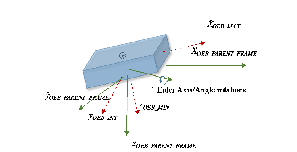
Figure F-1: Depiction of Optimally Enclosing Box and Definitions of MAX, INT, and MIN Orientation Vectors Relative to OEB Parent Frame
Note
Parent and body axis are shown in proximity to each other for display purposes only but could generally be in any orientation as specified by the quaternion.
A fixed orientation of the Optimally Encompassing Box with respect to the user-specified ‘OEB_PARENT_FRAME’ is defined using a quaternion that maps from the user-specified OEB_PARENT_FRAME to the Optimally Encompassing Box vector directions. The above figure shows the proper definitions and sign conventions. The resulting transformation sequence is:
Where the frame transformation matrix [M] is a function of the quaternion components:
The physical dimensions of the OEB (long, intermediate, and short dimensions) are specified via OEB_MAX, OEB_INT, and OEB_MIN, respectively.
The cross-sectional area is modeled in the OCM as a combination of two parameter types:
an attitude-independent, constant cross-sectional area (e.g., DRAG_CONST_AREA or SRP_CONST_AREA);
attitude-dependent cross-sectional area as viewed along the OEB x, y, and z axes (long, intermediate, and short dimension directions) via AREA_ALONG_OEB_MAX, AREA_ALONG_OEB_INT, and AREA_ALONG_OEB_MIN, respectively.
The analyst may use one or a combination of both parameter types to best represent the total cross-sectional area profile of the space object to be used in drag, lift, and SRP force estimates. The total cross-sectional area observed when viewed from an arbitrary unit-vector direction [x y z] could be:
For example, to model drag forces, a two-meter diameter spherical space object would be best modeled as a constant area (DRAG_CONST_AREA=3.1415m²) with all three AREA_ALONG_OEB parameters defaulting to zero. Conversely, a ten-meter long, 10 cm box-cross section gravity gradient boom would best be modeled by leaving DRAG_CONST_AREA defaulting to zero and setting AREA_ALONG_OEB_MAX = AREA_ALONG_OEB_INT = 1 m² and AREA_ALONG_OEB_MIN = 0.01 m². Finally, one can model a sphere encircling the gravity gradient boom’s centroid using a combination of these approaches by setting DRAG_CONST_AREA = 3.1415m², AREA_ALONG_OEB_MAX = AREA_ALONG_OEB_INT = 1 m² and AREA_ALONG_OEB_MIN = 0.01 m².
As a second example, when modeling SRP forces, it should be noted that many GEO spacecraft have very large solar arrays that dominate the total cross-sectional surface of the spacecraft. Importantly, these solar arrays are designed to remain as normal to the Sun as possible irrespective of current spacecraft bus orientation. As such, the cross-sectional area of these arrays is best portrayed in the OCM by setting SRP_CONST_AREA to the combined solar array surface area as observed along the Sun viewing vector, and the remaining bus cross-sectional areas can be set using the three attitude-dependent AREA_ALONG_OEB parameters.
F2 APPARENT-TO-ABSOLUTE VISUAL MAGNITUDE RELATIONSHIP
This section of the informative technical annex presents the relationships to be used to map apparent to absolute visual magnitude for inclusion in an OCM. These equations, based on reference [H8], examine signal magnitude for reflected illumination by a Resident Space Object (RSO) that is exoatmospheric, meaning that its illumination by the Sun is not reduced or impeded by atmospheric transmission losses. The equations do not account for spatial distribution across multiple detectors, which involves characterizing the Point Spread Function of the system.
Definitions:
\(A_{Target}\): Effective area of the target [m²].
\(E_{EntranceAperture}\): The point source irradiance reaching the sensor aperture [W/m²].
\(d_{sunToTarget}\): Distance from the sun to the target [m] (e.g., 1 AU = 1.4959787066 × 10¹¹ m).
\(d_{TargetToSensor}\): Distance from target to sensor [m].
\(dia_{Target}\): Effective diameter of the target, [m].
\(E_{sun}\): Exoatmospheric solar irradiance, nominally 1380 [W/m²] at 1 AU.
\(E_{target}\): Target Irradiance at Sensor without atmospheric loss [W/m²].
\(E_o\): Ref. Visual Magnitude (Vega) Irradiance [2.77894× 10⁻⁸ W/m²].
F: General shadowing term accounting for the penumbra region’s influence [unitless, 0 ≤ F ≤1, 0 = umbra, and 1 = full Sun illumination].
\(I_{sun}\): Solar Intensity ≈ 3.088374161 × 10²⁵ [W/sr].
\(I_{Target}\): Intensity of reflected energy from target treated as a point source [W/sr].
\(Phase(\phi)\): Geometric reflectance phase function [unitless, 0 < Phase(φ) ≤1].
\(\phi\): Critical Angle to the Sun (CATS) from sun to the sensor, as shown in figure F-2 and referenced to the observed target [rad].
\(\pi\): Pi constant.
\(\rho\): Reflectance of the target [between 0 (none) and 1 (perfect reflectance)].
\(\tau_{Atmosphere}\): Effective transmission of the atmosphere [unitless, 0 < τ ≤ 1].
Given an optical sensor’s measured target entrance aperture radiance:
or if \(VM_{apparent}\) known: \(E_{target} = E_o 10^{[- \frac{VM_{apparent}}{2.5}]}\)
Note
\(A_{Target}\) is undefined in umbra (F=0=darkness), or no reflection (ρ = 0).
If reflectance is unknown, one may assume a standard reference reflectance of fifteen percent.
From which an effective diameter of the physical object can be roughly approximated as:
From the above equations, \(VM_{absolute}\) ‘normalized’ to a 1 AU Sun-to-target distance, a phase angle of 0° and an example reference 40,000 km target-to-sensor distance (equivalent to a GEO satellite tracked at 15.6° elevation above the optical site’s local horizon), is obtained as:
F3 MANEUVER AND DUTY CYCLE DIAGRAMS
This section of the informative technical annex defines time-based and phase-angle-based duty cycle parameters.
A ‘duty cycle’ is a cycle of thruster operation that operates intermittently rather than continuously, having an ‘on’ interval followed by an ‘off’ interval.
Time-based duty cycle parameters
Time-based duty cycle parameters define a window of duty cycle operations, the actual execution interval and ‘ON’ and ‘OFF’ intervals, as shown in figure F-3.
Angle-based duty cycle parameters
Angle-based duty cycle parameters also define a window of duty cycle operations and actual execution interval and ‘ON’ and ‘OFF’ intervals, but in this case the ‘ON’ and ‘OFF’ intervals are triggered by angular limits as shown in figure F-4.
F4 ORBIT DETERMINATION GENERALIZED DILUTION OF PRECISION (GDOP) FORMULATION
This section of the informative technical annex defines the Generalized Dilution of Precision (GDoP) formulation used in the orbit determination section of the OCM.
As described in reference [H16], GDoP provides a method to assess the navigation performance over a time-integrated orbit solution. GDoP broadens the DoP concept from the more common instantaneous geometric or kinematic solution of multiple transmit sources at one time to a scenario associated with a receiver that can integrate metric range and/or Doppler (or range-rate) measurements over time, potentially from different transmit sources, to estimate the user’s orbital position and velocity state. It is defined as a function of the sum of information matrices to obtain an observability grammian associated with a set of metric tracking measurements collected over time.
The following equation for GDoP represents the uncertainty of an orbit state estimate as observed over time.
Where H is the measurement matrix modeled in the state estimate at the update time (i.e., the product of the observation and state transition matrices such that \(\tilde{H} = H \cdot \Phi\)), and W is a diagonal matrix of relative weights that represents the accuracy of the measurements. \(H^TWH_i\) represents the information matrix, the inverse of which is the covariance matrix. By summing over time, one obtains an estimate of the state uncertainty from the time-derived measurement set.
F5 EULER AXIS/ANGLE INTERPOLATION
The Euler Axis and Angle representation of Euler’s Theorem (see reference [H17] 10–14) is an effective way to interpolate a series of covariance matrices, reference frames or maneuvers, thrust, or acceleration vector directions.
Interpolation of a series of three-dimensional vectors:
As presented in reference [H17], and consistent with the nomenclature of reference [H1] where e₁, e₂, and e₃ represent the three vector components of axis of rotation ê and φ represents the angle of rotation, a time-based interpolation of adjacent unit vectors ÛA and ÛB in a reference frame can be undertaken as:
The axis of rotation ê can be obtained as: \(\hat{e} = \frac{\vec{U}_A \times \vec{U}_B}{|\vec{U}_A \times \vec{U}_B|}\).
Assuming a constant rotational rate during this interval, \(\phi(t) = \frac{(t-t_1)}{(t_2-t_1)} \cos^{-1}(\vec{U}_A \cdot \vec{U}_B)\).
The orthonormal rotation matrix [M(t)] is then:
From which the interpolated vector at time t is then v(t) = [M(t)]vA;
The accompanying vector magnitudes (e.g., eigenvalues or thrust or acceleration magnitudes) may be interpolated using Lagrange polynomials or linear expressions.
Interpolation of a series of reference (or covariance eigenvector) frames:
The eigenvector matrix [E(t)] contains the row-wise storage of the major, intermediate, and minor eigenvectors at time t, taking care to ensure that this ordered ‘triad’ of vectors adheres to the righthand rule. When interpolating between two eigenvector matrices [E₁] and [E₂], derived from two adjacent covariance matrices, respectively, [E(t)] can be evaluated as:
The rotation occurring between [E₁] and [E₂] is: [MBA] = [E₂][E₁]ᵀ;
Compute σ = (MBA₁₁ + MBA₂₂ + MBA₃₃);
The angle of rotation from A to B is: \(\phi_{BA} = \cos^{-1}[\frac{1}{2}(\sigma - 1)]\);
Exercising caution to accommodate nonunique cases (when sin φ = 0) as described in reference [H17], the axis of rotation
\[\hat{e} = [\frac{(MBA_{23}-MBA_{32})}{2\sin\phi} \frac{(MBA_{31}-MBA_{13})}{2\sin\phi} \frac{(MBA_{12}-MBA_{21})}{2\sin\phi}]\]The angle of rotation at time t is \(\phi(t) = (\frac{t-t_1}{t_2-t_1})\phi_{BA}\);
[M(t)] can be computed using the above expression in step (3);
And finally, the eigenvector matrix [E(t)] = [M(t)][E₁];
When interpolating a series of covariance matrices, the accompanying eigenvalues may be interpolated using Lagrange polynomials or linear expressions.
F6 REGULAR EXPRESSIONS FOR VALIDATION AND INGEST OF ODMS
To accomplish validation and ingest of KVN versions of the ODM, the use of Regular Expressions (referred to as ‘Regex’) is strongly encouraged whenever possible. Regex offers a detailed and rigorous way to ensure proper validation, interpretation, and conformace to Orbit Data Message content. Most programming languages support the Regex feature, including C#, C++, Delphi, HTML5, Java and Javascript, MySQL, Oracle, PCRE, Perl, PHP, PowerShell, Python, R, Ruby, Scala, TCL, VBscript, Visual Basic, and XML Schema.
While these RegEx sequences can provide a good level of validation of the entries, the reader is cautioned that using them on a long series of orbit or covariance data can be very inefficient and slow. RegEx sequences are best utilized on individual values such as Keyword = SingleValue.
Sample Regular Expression for ‘Keyword = CCSDS Date/Time Format’
The CCSDS Timecode format specified in 7.5.10 provides a convenient illustration of the power of using regular expressions. The color-coded Regex string below may be used to readily match any general ODM KVN line that sets a KVN keyword to a Timecode value. The group naming capability (color-coded in green below) inherent in Regex is particularly useful, by which the keyword, year, month, day, hour, minute, and second can be readily extracted and processed. As shown in figure F-5, this Regex sequence enforces the requirement that KVN keywords must be uppercase and can only consist of letters A-Z, digits 0-9, or underscores. It should be noted that in this expression, the optional inclusion by the message creator of one or more white space characters with the ‘(s*)?’ sequences allow for maximum flexibility while still retaining a rigorous validation.
Note
In some languages, ‘^’ and ‘$’ matching at string line breaks must explicitly be enabled to process a string containing a series of lines of the message.
Regex Pattern Matching Sequence:
Applying the above CCSDS Timecode Regex to a file containing the string ‘CREATION_DATE = 2020-09-13T00:09:47.059345’ as an example, figure F-6 illustrates how this Regex expression is used to rigorously validate and match the string and identify the specified group names.
Sample Regular Expression for ‘Keyword = NonDecimalString’
Another common and useful Regex addresses the setting of keywords to a free-text string. Consistent with requirements for KVN values as specified in 7.5, the Regex shown in figure F-7 matches this sequence.
Sample Regular Expression for ‘Keyword = FreeTextString’
Free-text strings that are contain exclusively uppercase or lowercase alphabetical characters, numbers, and/or the decimal point, hyphen, space or underscore characters may be matched as follows. It should be noted that the inclusion of a decimal point in this Regex sequence means that numerical KVN values can be matched with potentially unintended consequences; numbers should be specifically matched as a number (as shown below). Consistent with requirements for KVN values as specified in 7.5, the Regex shown in figure F-8 matches this sequence.
Sample Regular Expression for ‘Keyword = CCSDS Numerical Value with optional units’
Consistent with the requirements set forth in 7.5.4 through 7.5.7, KVN values that are integers or non-integer fixed or floating-point numbers may be matched with the Regex sequence provided in figure F-9, with named groups ‘keyword’, ‘value’, and ‘units’ set accordingly:
Sample Regular Expression for ‘Keyword = Multipartite CCSDS Numerical Values’
For orbit, covariance, and/or maneuver lines providing a multipartite sequence of numerical values, the Regex pattern provided in figure F-10 may be used (in this example, to capture and set value1, value2, and value3 for a 3-element set of numbers):
F7 SPECIFIC ENERGY DISSIPATION RATE (SEDR) FORMULATION
An orbit’s Specific Energy Dissipation Rate (SEDR) represents the amount of energy (W/kg) being removed from a satellite’s orbit by atmospheric drag. It is a very useful metric for characterizing satellites since it accounts for both the drag environment (atmospheric density) and the ‘area to mass ratio’ of the specific object. It does this by including drag acceleration in the computation. Drag acceleration is proportional to atmospheric density and to satellite area to mass.
SEDR is computed as follows:
Instantaneous SEDR at time t is given by
where, \(\vec{A}_D\) = drag acceleration vector (inertial) \(\vec{V}\) = velocity vector (inertial)
Average SEDR over the orbit determination interval is given by
where, to correctly average over a complete orbital revolution, T is an integer multiple of the satellite period. This consideration is primarily for eccentric orbits. Aside from this consideration, T is the orbit determination interval.
F8 ORBIT DETERMINATION PARAMETERS
F8.1 GENERAL
Satellite Orbit Determination (OD) estimates the position and velocity of an orbiting object from discrete observations (for greater detail, see reference [H7]). The set of observations includes external measurements from terrestrial or space-based sensors and measurements from instruments on the satellite itself. Satellite orbit propagation estimates the future state of motion of a satellite whose orbit has been determined from past observations. Though a satellite’s motion is described by a set of ideal equations of motion representing physical hypotheses, the observations used in OD are subject to systematic and random uncertainties. Therefore OD and propagation are probabilistic and can only approximately describe the satellite’s motion. The degree of approximation that can be tolerated depends on the intended use of the orbital information.
Satellite owners/operators employ different techniques to determine orbits from active and passive observations, such that the same data inputs lead to different predictions when they are used in different models. Satellite owners/operators often accept orbit descriptions developed using physical models that others employ. Differences in orbit predictions caused using different physical models and numerical techniques can be significant.
A spacecraft is influenced by a variety of external forces, including terrestrial gravity, atmospheric drag, multibody gravitation, solar radiation pressure, tides, and spacecraft thrusters. Selection of forces for modelling depends on the accuracy and precision required by the OD process and the amount of available data. The complex modelling of these forces results in a highly nonlinear set of dynamical equations. Many physical and computational uncertainties limit the accuracy and precision of the spacecraft state that can be determined. Similarly, the observational data are inherently nonlinear with respect to the state of motion of the spacecraft, and some influences might not have been included in models of the observation of the state of motion.
Satellite OD and propagation are stochastic estimation problems because observations are inherently noisy and uncertain and because not all phenomena that influence satellite motion are clearly discernible. Estimation is the process of extracting a desired time-varying signal from statistically noisy observations accumulated over time. Estimation encompasses data smoothing, which is statistical inference from past observations; filtering, which infers the signal from past observations and current observations; and prediction or propagation, which employs past and current observations to infer the future of the signal.
F8.2 INITIAL OD
Initial OD (IOD) methods input tracking measurements with tracking platform locations, and output spacecraft position and velocity estimates. No a priori orbit estimate is required. Associated solution error magnitudes can be very large. IOD methods are sometimes nonlinear methods and are often trivial to implement. Measurement editing is typically not performed during IOD calculations because there are insufficient observations.
F8.3 METHODS FOR SUBSEQUENT OD
F8.3.1 Least Squares Differential Correction
Least Squares (LS) methods input tracking measurements with tracking platform locations and an a priori orbit estimate and output a refined orbit estimate. Associated solution error magnitudes are small when compared to IOD outputs. LS methods consist of an iterative sequence of corrections where sequence convergence is defined as a function of tracking measurement residual Root Mean Square (RMS). Each correction is characterized by a minimization of the sum of squares of tracking measurement residuals. The LS method was derived first by Gauss in 1795 and then independently by Legendre.
F8.3.2 Sequential Processing
Sequential Processing (SP) methods are distinguished from LS processing methods in that batches of data are considered sequentially, collecting a set of observations over a specified time interval and batch-processing one interval after the next. SP can be thought of as a moving time window whose contents are captured and processed at intervals, independent of previously processed batches of data. The analysis does not include process noise inputs and calculations. It is in no way equivalent to filter processing, in which each new observation is added to past observations, improving estimates in a rigorous, traceable manner.
F8.3.3 Filter Processing
Filter methods output refined state estimates sequentially at each observation time. Filter methods are forward-time recursive sequential methods consisting of a repeating pattern of time updates of the state of motion estimate and measurement updates of the state of motion estimate. The filter time update propagates the state estimate forward, and the filter measurement update incorporates the next measurement. The recursive pattern includes an important interval of filter initialization. Filter-smoother methods are backward-time recursive sequential methods consisting of a repeating pattern of state estimate refinement using filter outputs and backwards transition. Time transitions for both filter and smoother are dominated most significantly by numerical orbit propagators. The search for sequential processing was begun by Wiener, Kalman, Bucy, and others.
F8.4 REQUIRED INFORMATION FOR ORBIT DETERMINATION
F8.4.1 Observations
When observation data are communicated for collaborative or independent determination of satellite orbits, it is important to convey the observation types upon which that information is based. Ground-based, airborne, and space-based sensor observations are routinely used in orbit determination. These are conveyed in the CCSDS navigation family of messages using the TDM (reference [9]). Many of these parameters are discussed in greater detail in reference [H7].
The following table describes some of the various observation types and sources.
Table F-1: Space Surveillance Observation Product Description
Content |
Source |
|---|---|
two angles and slant range |
Radars |
two angles |
Baker-Nunn cameras, telescopes, binoculars, visual sightings |
Azimuth |
Direction finders, radio antenna, Radio telescope |
Time of closest approach |
Radars, radio receivers [for transmitting (Doppler) satellites], relay satellite |
Range, angles, and rates |
Radars, radio antenna, radio telescope |
Pseudorange and carrier phase, as well as single, double, and triple differences of these basic measurement types |
GPS or onboard inertial sensors |
Direction cosines |
Interferometric radars |
F8.4.2 Observation Location Information
When data are communicated for collaborative or independent determination of satellite orbits, the following information about the observation location and measuring devices is important:
facility location latitude, longitude, altitude, and the reference from which such are measured, (e.g., WGS-84);
calibration/correction values associated with the ground path;
tracking station identification (ID);
elevation cutoff;
measurement biases;
clock and/or almanac information.
F8.4.3 Satellite Information
When performing OD using active transponder ranging, the transponder delay must be provided.
F8.4.4 Estimation Parameters and Control
When data are communicated for collaborative or independent determination of satellite orbits, the following information about estimation parameters and control are necessary, as described in 6.2.10:
estimation parameters;
global force model controls;
integration controls;
database controls;
observation uncertainties.
F8.4.5 Force Model Settings
F8.4.5.1 General
Spacecraft are affected by conservative and non-conservative forces. Non-conservative phenomena dissipate spacecraft energy, for example by doing work on and heating the atmosphere, as described in 6.2.9.
F8.4.5.2 Gravity
Central body gravitational fields are typically described using terms of a Jacobi polynomial expansion of finite order and degree. Jacobi polynomials are a complete, orthonormal set over the unit sphere. There are two angular degrees of freedom, equivalent to latitude and longitude. Any analytic function within that space can be represented by a weighted doubly infinite series of Jacobi polynomials.
Two-body motion or Keplerian motion considers only the point-mass gravity of the attracting body. Both the spacecraft and the central body are considered point masses, with all mass concentrated at their centres of mass. This is the lowest-order zonal harmonic approximation.
A J2 zonal perturbation (first order) accounts for secular (constant rate over time) variations in the orbit elements due to central body oblateness, mainly nodal precession and rotation of the semi-major axis of orbit elements that are otherwise those of unperturbed, Newtonian orbits. J2 is a zonal harmonic coefficient in an infinite Jacobi polynomial series representation of the central body’s gravity field. The even zonal harmonic coefficients of the gravity field are the only coefficients that result in secular changes in satellite orbital elements. The J2 propagator includes only the dominant first-order secular effects.
For generalized spherical harmonics, it is impractical to determine the weights (coefficients) for a mathematically complete Jacobi polynomial series representation; therefore the series is truncated at meaningful (in terms of precision of the representation of the gravity field) order (latitudinal) and degree (longitudinal). Whenever practical, it is recommended to use the full degree and order of the determined spherical harmonics field, as further truncation leads to introduction of non-conservative forces and deviation from the intended fidelity of the gravitational model.
If the order and degree are equal, the truncation is ‘square’. Since gravitational and other perturbations are not necessarily symmetrical in latitude and longitude, the best approximation for a given application is not necessarily square. The GRAVITY_MODEL keyword in 6.2.9 can specify (independently) the degree and order that are used.
Static elements of the gravity field are the gravitation of the fixed portions of the distribution of the Earth’s mass. The static gravity field is not uniform. Dynamic elements of the gravity are caused by the fluid elements of the Earth’s core and by variations in the distribution of water. There are solid and ocean tides. The OCEAN_TIDES_MODEL and SOLID_TIDES_MODEL of 6.2.9 can be used to specify these settings.
Multibody gravitation: Certain phenomena only exist with more than two gravitationally interacting bodies. It is therefore important to describe information about third-body or multiple-body gravitational interactions if such are considered. The N_BODY_PERTURBATIONS keyword in 6.2.9 is used to specify which bodies were modelled.
F8.4.5.3 Atmospheric Resistance (‘Drag’)
F8.4.5.3.1 General
Gas-dynamic resistance can be a significant dissipative force in low altitude orbits about any body with a significant atmosphere, for example, Earth (LEOs), Venus, and Mars. It is usually sufficient to represent it as aerodynamic drag, the product of dynamic pressure, aggregated drag coefficient, and cross-sectional area.
F8.4.5.3.2 Drag Coefficient
Drag coefficient depends upon satellite geometry, orientation, and gas-dynamic regime described by Knudsen number (ratio of object characteristic dimension to gas mean free path) and Mach number (ratio of object speed to acoustic propagation speed). When describing how atmospheric resistance is represented, data providers provide the value of drag coefficient employed using the keyword in 6.2.9.
F8.4.5.3.3 Atmospheric Density Model
Density within the Earth’s atmosphere varies temporally and spatially. Those variations are important in LEO. Some acceptable and most-often used atmospheric density models are as follows (although many may be utilized, as specified by the ATMOSPHERIC_MODEL keyword in 6.2.9):
1976 Standard Harris-Priester;
Jacchia 1970 and 1971;
Jaccia-Roberts;
Mass-Spectrometer-Incoherent-Scatter (MSIS) model, in several versions and extensions;
Mars Global Reference Atmosphere Model (MARSGRAM);
Venus Global Reference Atmosphere Model (VENUSGRAM).
These models typically require measurable input parameters that are ‘proxies’ for the variation of atmospheric parameters. These include solar flux/geomagnetic particle flux, which can be inferred from the meteorological observables as set by the keyword SW_DATA_SOURCE or FIXED_YYYYY of 6.2.9:
daily F10.7;
average F10.7; and
geomagnetic index.
F8.4.5.4 Radiation Pressure
Momentum transfer from photons to satellites can be an important force for High Earth Orbits (HEOs), cislunar trajectories, and interplanetary trajectories. For solar sail missions, such radiation pressure is the primary source of propulsion. Radiation pressure depends on the area and surface characteristics of the satellite and the nature of the incident radiative fluxes. The Sun is the predominant direct source of electromagnetic radiation, but the Earth and the Moon also emit and reflect electromagnetic radiation. The keywords provided in 6.2.9 (SHADOW_BODIES, SRP_MODEL, ALBEDO_MODEL, ALBEDO_GRID_SIZE) allow the user to specify radiation pressure settings used in the OD and orbit propagation regarding:
solar radiation pressure coefficient;
area-to-mass ratio;
satellite reflectivity;
shadow and shape factor models;
eclipse models (cylindrical, dual-cone);
albedo and intensity at the satellite.
F8.4.6 Orbit Propagation
Orbit propagation or prediction has evolved synchronously with advances in computational capability. Initially, force models were greatly simplified, and most important non-gravitational forces were approximated analytically. These generally linearized approaches were valid only over short intervals or for small variations from two-body Keplerian motion.
Even when more precise numerical integration became feasible, execution times were often too long, and computation was too expensive to employ numerical integration on a regular basis. Semi-analytical techniques emerged that reduced numerical complexity and maintained run speed efficiency (with some compromise to precision) by providing formulae from which significant elements of the propagation workflow could be extracted.
Purely numerical integration of force models (i.e., not employing singly or doubly averaged physical approximations to describe important physical phenomena) are degraded primarily to the numerical phenomena degradation common to all discrete computations.
Analytical, numerical, and semi-analytical orbit propagation techniques are all known as ‘orbit propagators’.
F8.4.7 Orbit Elements
Orbit elements are the sets of parameters that emerge from the smoothing, filtering, or predictive estimation schemes. Six independent quantities and orbit elements describe the orbit of a satellite. A seventh variable designates the satellite position at a specific time of interest (epoch). There are many different sets of orbit elements (see orbit element set type; selected per annex B, subsection B7). Each is best suited for a particular application, such as aiming antennas, ease of manipulation in various coordinate systems, or estimating orbits from different types of measurements.
The traditionally used set of orbital elements is called the set of Keplerian elements. Keplerian elements parameters can be encoded as text in several formats. In semi-analytical propagation, mean orbit elements are often used; the most common of them is as conveyed in the NASA/NORAD TLE format, originally designed for use with 80-column punched cards (but still in use because it is the most common format).
ANNEX G
(INFORMATIVE)
ODM EXAMPLES
G1 OVERVIEW
The following are examples of OPMs.
G2 OPM EXAMPLES IN KVN
The following figures are examples of OPMs in KVN format. The first has only a state; the second has state, Keplerian elements, and maneuvers; and the third and fourth include the position/velocity covariance matrix.
CCSDS_OPM_VERS = 3.0
CREATION_DATE = 2022-11-06T09:23:57
ORIGINATOR = JAXA
COMMENT GEOCENTRIC, CARTESIAN, EARTH FIXED
OBJECT_NAME = OSPREY 5
OBJECT_ID = 1998-999A
CENTER_NAME = EARTH
REF_FRAME = ITRF2000
TIME_SYSTEM = UTC
EPOCH = 2022-12-18T14:28:15.1172
X = 6503.514000
Y = 1239.647000
Z = -717.490000
X_DOT = -0.873160
Y_DOT = 8.740420
Z_DOT = -4.191076
MASS = 3000.000000
SOLAR_RAD_AREA = 18.770000
SOLAR_RAD_COEFF = 1.000000
DRAG_AREA = 18.770000
DRAG_COEFF = 2.500000
G4 OMM EXAMPLES IN KVN
The following figures are examples of OMMs in KVN format.
GOES 9 [P]
1 23581U 95025A   07064.44075725 -.00000113  00000-0  10000-3 0  9250
2 23581 003.0539 081.7939 0005013 249.2363 150.1602 01.00273272 43169
CCSDS_OMM_VERS = 3.0
CREATION_DATE = 2020-065T16:00:00
ORIGINATOR    = NOAA
MESSAGE_ID    = OMM 202013719185
OBJECT_NAME   = GOES 9
OBJECT_ID     = 1995-025A
CENTER_NAME   = EARTH
REF_FRAME     = TEME
TIME_SYSTEM   = UTC
MEAN_ELEMENT_THEORY = SGP/SGP4
EPOCH         = 2020-064T10:34:41.4264
MEAN_MOTION   = 1.00273272
ECCENTRICITY  = 0.0005013
INCLINATION   = 3.0539
RA_OF_ASC_NODE= 81.7939
ARG_OF_PERICENTER = 249.2363
MEAN_ANOMALY  = 150.1602
GM            = 398600.8
EPHEMERIS_TYPE= 0
CLASSIFICATION_TYPE = U
NORAD_CAT_ID  = 23581
ELEMENT_SET_NO= 0925
REV_AT_EPOCH  = 4316
BSTAR         = 0.0001
MEAN_MOTION_DOT = -0.00000113
MEAN_MOTION_DDOT = 0.0
G6 OEM EXAMPLES IN KVN
The following figures are examples of OEMs in KVN format. Some ephemeris data lines have been omitted to save space.
Figure G-11: OEM Example with No Acceleration, No Covariance
CCSDS_OEM_VERS = 3.0
CREATION_DATE = 1996-11-04T17:22:31
ORIGINATOR    = NASA/JPL

META_START
OBJECT_NAME   = MARS GLOBAL SURVEYOR
OBJECT_ID     = 1996-062A
CENTER_NAME   = MARS BARYCENTER
REF_FRAME     = EME2000
TIME_SYSTEM   = UTC
START_TIME    = 2019-12-18T12:00:00.331
USEABLE_START_TIME = 2019-12-18T12:10:00.331
USEABLE_STOP_TIME = 2019-12-28T21:23:00.331
STOP_TIME     = 2019-12-28T21:28:00.331
INTERPOLATION = HERMITE
INTERPOLATION_DEGREE = 7
META_STOP
COMMENT This file was produced by M.R. Pigs, OSAR NAV/JPL, 2019NOV 04. It is
COMMENT to be used for DSN scheduling purposes only.

2019-12-18T12:00:00.331 2789.619 -280.045 -1746.755 4.73372 -2.49586 -1.04195
2019-12-18T12:01:00.331 2783.419 -308.143 -1877.071 5.18604 -2.42124 -1.99608
2019-12-18T12:02:00.331 2776.033 -336.859 -2008.682 5.63678 -2.33951 -1.94687
< intervening data records omitted here >
2019-12-28T21:28:00.331 -3881.024 563.959 -682.773 -3.28827 -3.66735 1.63861
META_START
OBJECT_NAME   = MARS GLOBAL SURVEYOR
OBJECT_ID     = 1996-062A
CENTER_NAME   = MARS BARYCENTER
REF_FRAME     = EME2000
TIME_SYSTEM   = UTC
START_TIME    = 2019-12-28T21:29:07.267
USEABLE_START_TIME = 2019-12-28T22:08:02.5
USEABLE_STOP_TIME = 2019-12-30T01:18:02.5
STOP_TIME     = 2019-12-30T01:28:02.267
INTERPOLATION = HERMITE
INTERPOLATION_DEGREE = 7
META_STOP
COMMENT This block begins after trajectory correction maneuver TCM-3.
2019-12-28T21:29:07.267 -2432.166 -063.042 1742.754 7.33702 -3.495867 -1.041945
2019-12-28T21:59:02.267 -2445.234 -878.141 1873.073 1.86043 -3.421256 -0.996366
2019-12-28T22:00:02.267 -2458.079 -683.858 2007.684 6.36786 -3.339563 -0.946654
< intervening data records omitted here >
2019-12-30T01:28:02.267 2164.375 1115.811 -688.131 -3.53328 -2.88452 0.88535
G8 OCM EXAMPLES IN KVN
The following figures are examples of OCMs in KVN format. The first has only a time history of orbital states and constitutes a minimal content OCM. The second includes space object characteristics and Perturbations Specifications; the third includes a time series of maneuvers, a time history of Cartesian position and velocity trajectory states, followed by a time history of Keplerian elements; and the fourth includes a time series of covariance matrices.
G10 AGGREGATING MULTIPLE ODMS IN A SINGLE NDM XML FILE
The following examples illustrate how multiple Orbit Data Messages can be aggregated in a single XML file using the NDM ‘combined instantiation’ schema.
Figure G-21: Aggregating Multiple ODMs into a Single NDM File
<?xml version="1.0" encoding="UTF-8"?>
<ndm xmlns:xsi="http://www.w3.org/2001/XMLSchema-instance"
     xsi:noNamespaceSchemaLocation="https://sanaregistry.org/r/ndmxml_unqualified/ndmxml-3.0.0-master-3.0.xsd"
     version="3.0">
  <header>
    <COMMENT>GENERATED VIA SPACE-TRACK.ORG API</COMMENT>
    <CREATION_DATE>2020-05-16T14:00:01</CREATION_DATE>
    <ORIGINATOR>18 SPCS</ORIGINATOR>
  </header>
  <body>
    <segment>
      <metadata>
        <OBJECT_NAME>STARLINK-1073</OBJECT_NAME>
        <OBJECT_ID>2020-001A</OBJECT_ID>
        <CENTER_NAME>EARTH</CENTER_NAME>
        <REF_FRAME>TEME</REF_FRAME>
        <TIME_SYSTEM>UTC</TIME_SYSTEM>
        <MEAN_ELEMENT_THEORY>SGP4</MEAN_ELEMENT_THEORY>
      </metadata>
      <data>
        <meanElements>
          <EPOCH>2020-05-16T14:00:01</EPOCH>
          <MEAN_MOTION>15.05566242</MEAN_MOTION>
          <ECCENTRICITY>0.0001225</ECCENTRICITY>
          <INCLINATION>52.9981</INCLINATION>
          <RA_OF_ASC_NODE>157.6133</RA_OF_ASC_NODE>
          <ARG_OF_PERICENTER>93.35</ARG_OF_PERICENTER>
          <MEAN_ANOMALY>295.8599</MEAN_ANOMALY>
        </meanElements>
        <tleParameters>
          <EPHEMERIS_TYPE>0</EPHEMERIS_TYPE>
          <CLASSIFICATION_TYPE>U</CLASSIFICATION_TYPE>
          <NORAD_CAT_ID>44914</NORAD_CAT_ID>
          <ELEMENT_SET_NO>999</ELEMENT_SET_NO>
          <REV_AT_EPOCH>176</REV_AT_EPOCH>
          <BSTAR>0.00057678</BSTAR>
          <MEAN_MOTION_DOT>0.00008131</MEAN_MOTION_DOT>
          <MEAN_MOTION_DDOT>0</MEAN_MOTION_DDOT>
        </tleParameters>
        <userDefinedParameters>
          <USER_DEFINED parameter="TLE_LINE0">0 STARLINK-1073</USER_DEFINED>
          <USER_DEFINED parameter="TLE_LINE1">1 44914U 20211A 20137.58334491 +.00008131 +00000-0 +57678-3 0 9994</USER_DEFINED>
          <USER_DEFINED parameter="TLE_LINE2">2 44914 052.9981 157.6133 0001225 093.3500 295.8599 15.05566242001761</USER_DEFINED>
        </userDefinedParameters>
      </data>
    </segment>
    <segment>
      <metadata>
        <OBJECT_NAME>STARLINK-1084</OBJECT_NAME>
        <OBJECT_ID>2020-001B</OBJECT_ID>
        <CENTER_NAME>EARTH</CENTER_NAME>
        <REF_FRAME>TEME</REF_FRAME>
        <TIME_SYSTEM>UTC</TIME_SYSTEM>
        <MEAN_ELEMENT_THEORY>SGP4</MEAN_ELEMENT_THEORY>
      </metadata>
      <data>
        <meanElements>
          <EPOCH>2020-05-16T14:00:01</EPOCH>
          <MEAN_MOTION>15.05603711</MEAN_MOTION>
          <ECCENTRICITY>0.000126</ECCENTRICITY>
          <INCLINATION>52.9991</INCLINATION>
          <RA_OF_ASC_NODE>157.611</RA_OF_ASC_NODE>
          <ARG_OF_PERICENTER>75.9191</ARG_OF_PERICENTER>
          <MEAN_ANOMALY>151.2104</MEAN_ANOMALY>
        </meanElements>
        <tleParameters>
          <EPHEMERIS_TYPE>0</EPHEMERIS_TYPE>
          <CLASSIFICATION_TYPE>U</CLASSIFICATION_TYPE>
          <NORAD_CAT_ID>44915</NORAD_CAT_ID>
          <ELEMENT_SET_NO>999</ELEMENT_SET_NO>
          <REV_AT_EPOCH>1986</REV_AT_EPOCH>
          <BSTAR>0.0006442</BSTAR>
          <MEAN_MOTION_DOT>0.00009125</MEAN_MOTION_DOT>
          <MEAN_MOTION_DDOT>0</MEAN_MOTION_DDOT>
        </tleParameters>
        <userDefinedParameters>
          <USER_DEFINED parameter="TLE_LINE0">0 STARLINK-1084</USER_DEFINED>
          <USER_DEFINED parameter="TLE_LINE1">1 44915U 20211B 20137.58334491 +.00009125 +00000-0 +64420-3 0 9992</USER_DEFINED>
          <USER_DEFINED parameter="TLE_LINE2">2 44915 052.9991 157.6110 0001260 075.9191 151.2104 15.05603711019869</USER_DEFINED>
        </userDefinedParameters>
      </data>
    </segment>
    <!-- Figure G-21: Aggregating Multiple ODMs into a Single NDM File (Continued) -->
    <segment>
      <metadata>
        <OBJECT_NAME>STARLINK-1097</OBJECT_NAME>
        <OBJECT_ID>2020-001C</OBJECT_ID>
        <CENTER_NAME>EARTH</CENTER_NAME>
        <REF_FRAME>TEME</REF_FRAME>
        <TIME_SYSTEM>UTC</TIME_SYSTEM>
        <MEAN_ELEMENT_THEORY>SGP4</MEAN_ELEMENT_THEORY>
      </metadata>
      <data>
        <meanElements>
          <EPOCH>2020-05-16T14:00:01</EPOCH>
          <MEAN_MOTION>15.05559315</MEAN_MOTION>
          <ECCENTRICITY>0.0001361</ECCENTRICITY>
          <INCLINATION>52.999</INCLINATION>
          <RA_OF_ASC_NODE>157.6123</RA_OF_ASC_NODE>
          <ARG_OF_PERICENTER>94.2334</ARG_OF_PERICENTER>
          <MEAN_ANOMALY>78.9025</MEAN_ANOMALY>
        </meanElements>
        <tleParameters>
          <EPHEMERIS_TYPE>0</EPHEMERIS_TYPE>
          <CLASSIFICATION_TYPE>U</CLASSIFICATION_TYPE>
          <NORAD_CAT_ID>44916</NORAD_CAT_ID>
          <ELEMENT_SET_NO>999</ELEMENT_SET_NO>
          <REV_AT_EPOCH>1986</REV_AT_EPOCH>
          <BSTAR>0.00072742</BSTAR>
          <MEAN_MOTION_DOT>0.00010329</MEAN_MOTION_DOT>
          <MEAN_MOTION_DDOT>0</MEAN_MOTION_DDOT>
        </tleParameters>
        <userDefinedParameters>
          <USER_DEFINED parameter="TLE_LINE0">0 STARLINK-1097</USER_DEFINED>
          <USER_DEFINED parameter="TLE_LINE1">1 44916U 20211C 20137.58334491 +.00010329 +00000-0 +72742-3 0 9997</USER_DEFINED>
          <USER_DEFINED parameter="TLE_LINE2">2 44916 052.9990 157.6123 0001361 094.2334 078.9025 15.05559315019865</USER_DEFINED>
        </userDefinedParameters>
      </data>
    </segment>
  </body>
</ndm>
Figure G-22: Aggregating OPM, OMM, OEM, and OCM in a Single Navigation Data Message XML
<?xml version="1.0" encoding="UTF-8"?>
<ndm xmlns:xsi="http://www.w3.org/2001/XMLSchema-instance"
     xsi:noNamespaceSchemaLocation="https://sanaregistry.org/r/ndmxml_unqualified/ndmxml-3.0.0-master-3.0.xsd"
     version="3.0">
  <header>
    <COMMENT>This example combines an OPM, OMM, OEM, and OCM in a single Navigation Data Message XML.</COMMENT>
    <COMMENT>NOTE - In this case the messages are unrelated, but show how, in principle, related </COMMENT>
    <COMMENT>messages could be combined to satisfy a specific use case.</COMMENT>
  </header>
  <body>
    <opm id="CCSDS_OPM_VERS" version="3.0">
      <header>
        <COMMENT>Example Orbit Parameter Message</COMMENT>
        <COMMENT>The OPM includes a set of orbital elements at time t, and an impulsive maneuver design with MAN_EPOCH_IGNITION = t.</COMMENT>
        <CREATION_DATE>2009-05-12T13:06:00</CREATION_DATE>
        <ORIGINATOR>NASA</ORIGINATOR>
      </header>
      <segment>
        <metadata>
          <OBJECT_NAME>SOHO</OBJECT_NAME>
          <OBJECT_ID>2009-000A</OBJECT_ID>
          <CENTER_NAME>EARTH</CENTER_NAME>
          <REF_FRAME>EME2000</REF_FRAME>
          <TIME_SYSTEM>UTC</TIME_SYSTEM>
        </metadata>
        <data>
          <stateVector>
            <EPOCH>2009-05-12T15:30:00</EPOCH>
            <X>687754.36358524448</X>
            <Y>941287.85553999904</Y>
            <Z>520080.81101286016</Z>
            <X_DOT>-0.41396551860286032</X_DOT>
            <Y_DOT>0.29174462217893128</Y_DOT>
            <Z_DOT>0.11756781919443198</Z_DOT>
          </stateVector>
          <maneuverParameters>
            <COMMENT>The below contains information for the impulsive maneuver.</COMMENT>
            <MAN_EPOCH_IGNITION>2009-05-12T15:30:00</MAN_EPOCH_IGNITION>
            <MAN_DURATION>0</MAN_DURATION>
            <MAN_DELTA_MASS>-0.0252069575402913408</MAN_DELTA_MASS>
            <MAN_REF_FRAME>EME2000</MAN_REF_FRAME>
            <MAN_DV_1>0.000028562811624</MAN_DV_1>
            <MAN_DV_2>3.0883529021E-7</MAN_DV_2>
            <MAN_DV_3>1.4646782842E-8</MAN_DV_3>
          </maneuverParameters>
        </data>
      </segment>
    </opm>
    <omm id="CCSDS_OMM_VERS" version="3.0">
      <header>
        <COMMENT>Example Orbit Mean-Elements Message</COMMENT>
        <COMMENT>ODM PROTOTYPING FOR CCSDS 502.0-P-1.1 - TEST NUMBER 4</COMMENT>
        <CREATION_DATE>2009-091T16:00:00</CREATION_DATE>
        <ORIGINATOR>CNES</ORIGINATOR>
      </header>
      <segment>
        <metadata>
          <OBJECT_NAME>ISS-ZARYA</OBJECT_NAME>
          <OBJECT_ID>2022-067A</OBJECT_ID>
          <CENTER_NAME>EARTH</CENTER_NAME>
          <REF_FRAME>TEME</REF_FRAME>
          <TIME_SYSTEM>UTC</TIME_SYSTEM>
          <MEAN_ELEMENT_THEORY>SGP4</MEAN_ELEMENT_THEORY>
        </metadata>
        <data>
          <COMMENT>USAF SGP4 IS THE ONLY PROPAGATOR THAT SHOULD BE USED FOR THIS DATA</COMMENT>
          <meanElements>
            <EPOCH>2009-087T11:58:23.211264</EPOCH>
            <MEAN_MOTION>15.71784080</MEAN_MOTION>
            <ECCENTRICITY>0.0009738</ECCENTRICITY>
            <INCLINATION>51.6429</INCLINATION>
            <RA_OF_ASC_NODE>0.4159</RA_OF_ASC_NODE>
            <ARG_OF_PERICENTER>166.5533</ARG_OF_PERICENTER>
            <MEAN_ANOMALY>354.9076</MEAN_ANOMALY>
          </meanElements>
          <tleParameters>
            <EPHEMERIS_TYPE>0</EPHEMERIS_TYPE>
            <CLASSIFICATION_TYPE>U</CLASSIFICATION_TYPE>
            <NORAD_CAT_ID>25544</NORAD_CAT_ID>
            <ELEMENT_SET_NO>557</ELEMENT_SET_NO>
            <REV_AT_EPOCH>59325</REV_AT_EPOCH>
            <BSTAR>-0.21414E-3</BSTAR>
            <MEAN_MOTION_DOT>0.00027894</MEAN_MOTION_DOT>
            <MEAN_MOTION_DDOT>0.0</MEAN_MOTION_DDOT>
          </tleParameters>
        </data>
      </segment>
    </omm>
    <!-- Figure G-22: Aggregating OPM, OMM, OEM, and OCM in a Single Navigation Data Message XML (Continued) -->
    <oem id="CCSDS_OEM_VERS" version="3.0">
      <header>
        <COMMENT>Example Orbit Ephemeris Message</COMMENT>
        <CREATION_DATE>2009-02-05T10:09:12</CREATION_DATE>
        <ORIGINATOR>JAXA</ORIGINATOR>
      </header>
      <segment>
        <metadata>
          <OBJECT_NAME>SELENE</OBJECT_NAME>
          <OBJECT_ID>131</OBJECT_ID>
          <CENTER_NAME>EARTH</CENTER_NAME>
          <REF_FRAME>EME2000</REF_FRAME>
          <TIME_SYSTEM>UTC</TIME_SYSTEM>
          <START_TIME>2007-09-14T10:43:00.000000</START_TIME>
          <STOP_TIME>2007-09-14T10:47:00.000000</STOP_TIME>
          <INTERPOLATION>HERMITE</INTERPOLATION>
          <INTERPOLATION_DEGREE>7</INTERPOLATION_DEGREE>
        </metadata>
        <data>
          <stateVector>
            <EPOCH>2007-09-14T10:43:00.000000</EPOCH>
            <X>1.336886031675458E+03</X>
            <Y>9.480146566872711E+04</Y>
            <Z>3.266088528177066E+04</Z>
            <X_DOT>-6.305293974707967E-01</X_DOT>
            <Y_DOT>1.848864859994888E+00</Y_DOT>
            <Z_DOT>9.377640352829226E-01</Z_DOT>
          </stateVector>
          <stateVector>
            <EPOCH>2007-09-14T10:44:00.000000</EPOCH>
            <X>1.299053338219702E+03</X>
            <Y>9.491233015399727E+04</Y>
            <Z>3.271712789822781E+04</Z>
            <X_DOT>-6.305602161673365E-01</X_DOT>
            <Y_DOT>1.846618917569059E+00</Y_DOT>
            <Z_DOT>9.369900978163187E-01</Z_DOT>
          </stateVector>
          <stateVector>
            <EPOCH>2007-09-14T10:45:00.000000</EPOCH>
            <X>1.261218825877070E+03</X>
            <Y>9.502306005072314E+04</Y>
            <Z>3.277324123553684E+04</Z>
            <X_DOT>-6.305900282238581E-01</X_DOT>
            <Y_DOT>1.844378570838882E+00</Y_DOT>
            <Z_DOT>9.362176632629805E-01</Z_DOT>
          </stateVector>
          <stateVector>
            <EPOCH>2007-09-14T10:46:00.000000</EPOCH>
            <X>1.223382554832220E+03</X>
            <Y>9.513365569386665E+04</Y>
            <Z>3.282947404774766E+04</Z>
            <X_DOT>-6.306188407720047E-01</X_DOT>
            <Y_DOT>1.842143793832282E+00</Y_DOT>
            <Z_DOT>9.354467257772656E-01</Z_DOT>
          </stateVector>
          <stateVector>
            <EPOCH>2007-09-14T10:47:00.000000</EPOCH>
            <X>1.185544584842622E+03</X>
            <Y>9.524411741683590E+04</Y>
            <Z>3.288557776045905E+04</Z>
            <X_DOT>-6.30646660867719E-01</X_DOT>
            <Y_DOT>1.839914560746108E+00</Y_DOT>
            <Z_DOT>9.346772795446093E-01</Z_DOT>
          </stateVector>
        </data>
      </segment>
    </oem>
    <!-- Figure G-22: Aggregating OPM, OMM, OEM, and OCM in a Single Navigation Data Message XML (Continued) -->
    <ocm id="CCSDS_OCM_VERS" version="3.0">
      <header>
        <COMMENT>Example G-4 from OCM P2.40</COMMENT>
        <COMMENT>OCM example with multiple trajectory state time histories, a maneuver, OD, Cartesian and Keplerian ephemeris</COMMENT>
        <CREATION_DATE>2022-11-06T09:23:57</CREATION_DATE>
        <ORIGINATOR>JAPAN AEROSPACE EXPLORATION AGENCY</ORIGINATOR>
      </header>
      <body>
        <segment>
          <metadata>
            <OBJECT_NAME>OSPREY 5</OBJECT_NAME>
            <INTERNATIONAL_DESIGNATOR>2022-999A</INTERNATIONAL_DESIGNATOR>
            <CATALOG_NAME>CSPOC</CATALOG_NAME>
            <OBJECT_DESIGNATOR>98765</OBJECT_DESIGNATOR>
            <TIME_SYSTEM>UTC</TIME_SYSTEM>
            <EPOCH_TZERO>2022-12-18T14:28:15.1172</EPOCH_TZERO>
          </metadata>
          <data>
            <traj>
              <TRAJ_BASIS>PREDICTED</TRAJ_BASIS>
              <CENTER_NAME>EARTH</CENTER_NAME>
              <TRAJ_REF_FRAME>TOD_EARTH</TRAJ_REF_FRAME>
              <TRAJ_FRAME_EPOCH>2022-12-18T14:28:15.1172</TRAJ_FRAME_EPOCH>
              <USEABLE_START_TIME>2022-12-18T14:28:15.1172</USEABLE_START_TIME>
              <USEABLE_STOP_TIME>2022-12-18T14:28:45.1172</USEABLE_STOP_TIME>
              <TRAJ_TYPE>CARTPVA</TRAJ_TYPE>
              <TRAJ_UNITS>[km, km, km, km/s, km/s, km/s, km/s**2, km/s**2, km/s**2]</TRAJ_UNITS>
              <trajLine>0.0 2854.5 -2916.2 -5360.7 5.90 4.86 0.52 0.0037 -0.0038 -0.0070</trajLine>
              <trajLine>120.0 5478.6 434.3 -3862.5 2.50 5.87 4.29 0.0072 0.0006 -0.0051</trajLine>
              <trajLine>240.0 4146.0 -1655.8 -5038.3 4.80 5.58 2.16 0.0054 -0.0022 -0.0066</trajLine>
              <trajLine>500.0 -1553.4 -4848.7 -4406.5 6.73 1.01 -3.53 -0.002 -0.0063 -0.0058</trajLine>
            </traj>
            <traj>
              <TRAJ_BASIS>DETERMINED</TRAJ_BASIS>
              <CENTER_NAME>EARTH</CENTER_NAME>
              <TRAJ_REF_FRAME>J2000</TRAJ_REF_FRAME>
              <TRAJ_TYPE>KEPLERIAN</TRAJ_TYPE>
              <ORB_AVERAGING>OSCULATING</ORB_AVERAGING>
              <TRAJ_UNITS>[km, n/a, deg, deg, deg, deg, deg]</TRAJ_UNITS>
              <trajLine>0.000000 6600.0 .03 28.5 50.0 30.0 10.0</trajLine>
              <trajLine>120.000000 6600.0 .03 28.5 50.0 30.0 10.1</trajLine>
              <trajLine>240.000000 6600.0 .03 28.5 50.0 30.0 10.2</trajLine>
              <trajLine>500.000000 6600.0 .03 28.5 50.0 30.0 35.0</trajLine>
            </traj>
            <phys>
              <COMMENT>Spacecraft Physical Characteristics</COMMENT>
              <DRAG_CONST_AREA units="m**2">10.00</DRAG_CONST_AREA>
              <DRAG_COEFF_NOM>2.300</DRAG_COEFF_NOM>
              <WET_MASS units="kg">100.0</WET_MASS>
              <SRP_CONST_AREA units="m**2">4</SRP_CONST_AREA>
              <SOLAR_RAD_COEFF>1.3</SOLAR_RAD_COEFF>
            </phys>
            <man>
              <COMMENT>200 s of 10N thrust (in-track transitioning to radial)</COMMENT>
              <COMMENT>w/effic η=0.95, Isp=300s, 5% 1-sigma error</COMMENT>
              <MAN_ID>E W 20160305B</MAN_ID>
              <MAN_BASIS>CANDIDATE</MAN_BASIS>
              <MAN_DEVICE_ID>THR_01</MAN_DEVICE_ID>
              <MAN_PURPOSE>ORBIT</MAN_PURPOSE>
              <MAN_REF_FRAME>RSW_ROTATING</MAN_REF_FRAME>
              <MAN_COMPOSITION>TIME RELATIVE, MAN_DURA, THR_X, THR_Y, THR_Z, THR_EFFIC, THR_INTERP, ISP, THR_MAG_SIGMA</MAN_COMPOSITION>
              <MAN_UNITS>[s, N, N, N, n/a, n/a, s, %]</MAN_UNITS>
              <manLine>500.0 200.0 0.0 10.0 0.0 0.95 ON 300.0 5.0</manLine>
              <manLine>700.0 200.0 0.0 10.0 0.0 0.95 OFF 300.0 5.0</manLine>
            </man>
            <pert>
              <COMMENT>Perturbations specification</COMMENT>
              <GM>398600.4415</GM>
            </pert>
            <od>
              <COMMENT>Orbit Determination information</COMMENT>
              <OD_ID>OD #10059</OD_ID>
              <OD_PREV_ID>OD #10058</OD_PREV_ID>
              <OD_METHOD>BWLS: BAHN</OD_METHOD>
              <OD_EPOCH>2001-11-06T11:17:33</OD_EPOCH>
              <OBS_USED>273</OBS_USED>
              <TRACKS_USED>91</TRACKS_USED>
            </od>
          </data>
        </segment>
      </body>
    </ocm>
  </body>
</ndm>
ANNEX H
(INFORMATIVE)
INFORMATIVE REFERENCES
[H1] Navigation Data—Definitions and Conventions. Issue 4. Report Concerning Space Data System Standards (Green Book), CCSDS 500.0-G-4. Washington, D.C.: CCSDS, November 2019. [H2] “CelesTrak.” Center for Space Standards & Innovation (CSSI). http://celestrak.com/. [H3] David A. Vallado, et al. “Revisiting Spacetrack Report #3.” In Proceedings of the AIAA/AAS Astrodynamics Specialist Conference and Exhibit (AIAA 2006-6753). Reston, Virginia: AIAA, 2006. [H4] “Documentation.” SPICE: NASA’s Solar System Exploration Ancillary Information System. Navigation and Ancillary Information Facility (NAIF). http://naif.jpl.nasa.gov/naif/documentation.html. [H5] Ground Network Tracking and Acquisition Data Handbook. 453-HNDK-GN. Greenbelt, Maryland: Goddard Space Flight Center, May 2007. [H6] Daniel L. Oltrogge, T.S. Kelso, and John H. Seago. “Ephemeris Requirements for Space Situational Awareness.” In Proceedings of the 21st AAS/AIAA Space Flight Mechanics Meeting (13–17 February 2011, New Orleans, Louisiana), AAS 11-151. San Diego, California: Univelt, 2011. [H7] David A. Vallado. Fundamentals of Astrodynamics and Applications. 4th ed. Space Technology Library. El Segundo, California: Microcosm Press, 2013. [H8] Daniel L. Oltrogge, Patrick North, and Michael Nicolls. “Multi-Phenomenology Observation Network Evaluation Tool (MONET).” In Proceedings of the 15th AMOS Surveillance Technologies Conference (9–12 September 2014, Maui, Hawaii). Kihei, Hawaii: Maui Economic Development Board, 2014. [H9] Salvatore Alfano. “Orbital Covariance Interpolation.” In Proceedings of the 14th AAS/AIAA Space Flight Mechanics Meeting (8–12 February 2004, Maui, Hawaii), AAS 04-223. San Diego, California: Univelt, 2004. [H10] Sergei Tanygin. “Attitude Interpolation.” In Proceedings of the 13th AAS/AIAA Space Flight Mechanics Meeting (9–13 February 2003, Ponce, Puerto Rico), AAS 03-197. San Diego, California: Univelt, 2003. [H11] Sergei Tanygin. “Efficient Covariance Interpolation Using Blending of Approximate State Error Transitions.” In Proceedings of the 2013 AAS/AIAA Astrodynamics Specialist Conference (11–15 August 2013, Hilton Head, South Carolina), AAS 13- 762. San Diego, California: Univelt, 2013. [H12] James Woodburn and Sergei Tanygin. “Position Covariance Visualization.” In Proceedings of the 2002 AIAA/AAS Astrodynamics Specialist Conference and Exhibit (Monterey, California, Monterey, California), AIAA 2002-4985. Reston, Virginia: AIAA, 2002. [H13] Salvatore Alfano. “Variance-Covariance Significant Figure Reduction and Its Effect on Collision Probability Calculation.” In Proceedings of the 70th International Astronautical Congress (IAC) (21–25 October 2019, Washington D.C.), IAC-19- A6.2.8.51075. Paris: International Astronautical Federation, 2019. [H14] DISCOSweb. ESA. https://discosweb.esoc.esa.int/. [H15] Elliott D. Kaplan and Christopher Hegarty, eds. Understanding GPS/GNSS: Principles and Applications. GNSS Technology and Applications. Boston and London: Artech, 2017. [H16] Obed S. Sands, et al. “Dilution of Precision-Based Lunar Navigation Assessment for Dynamic Position Fixing.” In Proceedings of the 2006 National Technical Meeting of The Institute of Navigation (January 18–20, 2006, Monterey, California), 260–268. Manassas, Virginia: ION, 2006. [H17] Peter C. Hughes. Spacecraft Attitude Dynamics. New York: John Wiley and Sons, 1986.
ANNEX I
(INFORMATIVE)
ITEMS FOR AN INTERFACE CONTROL DOCUMENT
In several places in this document, there are references to items that should be specified in an Interface Control Document (ICD) between participants that supplements an exchange of ephemeris data. The ICD should be jointly produced by both participants in a cross-support involving the transfer of ephemeris data. This annex compiles those recommendations into a single section. Although the Orbit Data Messages described in this document may at times be used in situations in which participants have not negotiated ICDs, they should be developed and negotiated whenever specified in this Recommended Standard.
Item |
Section |
|---|---|
|
3.2, 4.2, 5.2, 6.2 |
|
annex B, subsection B6 |
|
annex C |
ANNEX J
(INFORMATIVE)
CHANGES VERSUS PREVIOUS VERSION
This annex lists the differences between ODM 2.0 and ODM 3.0. The differences are divided into those which affect the content of one or more of the orbit data messages, and those which only affect the document.
J1 CHANGES IN THE MESSAGES
The OCM was added to provide better support for ISO Technical Committee 20, Subcommittee 14 objectives (see section 6).
MESSAGE_ID was added to the OPM, OMM, and OEM to provide better satisfaction of requirement P10 (identification and annotation of messages).
EPHEMERIS_TYPE was updated in the OMM to reflect currently used numbering scheme.
BSTAR and MEAN_MOTION_DDOT fields are paired with BTERM and AGOM parameters to support the SGP and SGP4 propagators as well as the new SGP4-XP propagator, respectively.
J2 CHANGES IN THE DOCUMENT
A new CCSDS repository for normative keyword values for navigation messages has been created at the SANA Registry, accessible on the Internet at: https://sanaregistry.org/r/navigation_standard_normative_annexes/. (See annex B for details on the affected keywords and links to the content.)
Several annexes were added. Some are required by CCSDS rule changes, and some are for the provision of supplementary material.
Examples for OPM, OMM, and OEM that formerly appeared in sections 3, 4, and 5, respectively, have been moved to an informative annex.
The ‘Checklist ICD’ that was added in ODM Version 2 has been discontinued. This Checklist ICD, intended to convey information that the OPM, OEM, and OMM did not address, such as third-body perturbations, solar pressure model, solid tides, ocean tides, Earth albedo, and polar motion, has now been replaced by the material that can be specified in the Orbit Comprehensive Message.
7.8 COMMENTS IN THE ORBIT DATA MESSAGES
7.8.1 There are certain pieces of information that provide clarity and remove ambiguity about the interpretation of the information in a file yet are not standardized so as to fit cleanly into the ‘keyword = value’ paradigm. Rather than force the information to fit into a space limited to one line, the ODM producer should put further specifications and information into comments. Static information should be separately shared and/or mutually agreed upon between message exchange partners outside of the ODM.
7.8.2 Comments may be used to provide provenance information or to help describe dynamical events or other pertinent information associated with the data. This additional information is intended to aid in consistency checks and elaboration when needed but shall not be required for successful processing of a file.
7.8.3 For the OPM, OMM, OEM, and OCM, comment lines shall be optional.
7.8.4 Comment text may be in any case (or mix of case) desired by the user.
7.8.5 All comment lines shall begin with the ‘COMMENT’ keyword followed by at least one space. This keyword must appear on every comment line, not just the first such line. The remainder of the line shall be the comment value. White space shall be retained (shall be significant) in comment values.
7.8.6 Placement of comments shall be as specified in the tables in sections 3, 4, 5, and 6 that describe the OPM, OMM, OEM, and OCM keywords.
7.8.7 Comments in the OPM may appear in the OPM Header immediately after the ‘CCSDS_OPM_VERS’ keyword, at the very beginning of the OPM Metadata section, and at the beginning of a logical block in the OPM Data section. Comments must not appear between the components of any logical block in the OPM Data section.
Note
The logical blocks in the OPM Data section are indicated in table 3-3.
7.8.8 Comments in the OMM may appear in the OMM Header immediately after the ‘CCSDS_OMM_VERS’ keyword, at the very beginning of the OMM Metadata section, and at the beginning of a logical block in the OMM Data section. Comments must not appear between the components of any logical block in the OMM Data section.
Note
The logical blocks in the OMM Data section are indicated in table 4-3.
7.8.9 Comments in the OEM may appear in the OEM Header immediately after the ‘CCSDS_OEM_VERS’ keyword, at the very beginning of the OEM Metadata section (after the ‘META_START’ keyword), at the beginning of the OEM Ephemeris Data Section, and at the beginning of the OEM Covariance Data section (after the ‘COV_START’ keyword). Comment lines must not appear within any block of ephemeris lines or covariance matrix lines.
7.8.12 The following comments should be provided:
Information regarding the genesis, history, interpretation, intended use, etc., of the state vector, spacecraft, maneuver, or ephemeris that may be of use to the receiver of the OPM, OMM, OEM, or OCM:
Natural body ephemeris information: When the Earth is not the center of motion, the ephemerides of the planets, satellites, asteroids, and/or comets (including associated constants) consistent with the ODM should be identified so that the recipient can, in a consistent manner, make computations involving other centers:
OEM accuracy vs. efficiency: If the covariance data section of the OEM is not utilized, the producer of an OEM should report in comment lines what the expected accuracy of the ephemeris is, so the user can smooth or otherwise compress the data without affecting the accuracy of the trajectory. The OEM producer also should strive to achieve not only the best accuracy possible, considering prediction errors, but also consider the efficiency of the trajectory representation (e.g., step sizes of fractional seconds between ephemeris lines may be necessary for precision scientific reconstruction of an orbit, but are excessive from the standpoint of antenna pointing predicts generation).